HARGING YOUR E-BIKE BATTERY WITH A CAMPER VANHERE’S HOW
E-bikes are very much in vogue – something that has long been true of camping holidays, where e-bikes are becoming an increasingly popular piece of equipment. But how do things work out if an e-bike battery has to be charged on the camper van tour? In this blog post, we will show you how to charge your pedelec en route, what you have to bear in mind and what other equipment you will need.
OUT AND ABOUT IN A CAMPER VAN AND ON AN E-BIKE
and more people are taking their e-bikes on holiday so that they can discover their holiday destination on two wheels. It is no coincidence that numerous tourist destinations now specialize in e-bikers as a potential target group, offering specially marked routes and tour suggestions, for example.
Which is why more and more camping enthusiasts are taking their own electric bikes with them. And no wonder: your own pedelec offers a safer ride than renting a local bike. It can be easily transported in either the camper van or on its own bicycle rack. Once you have reached your destination, it noticeably broadens the range of action at your holiday spot.
HOW DO I CHARGE MY E-BIKE EN ROUTE?
But what happens when you run out of juice and need to charge the battery? In principle, there are several options with a camper van. The most obvious is certainly the pitch on the respective campsite: the local infrastructure is easy to use and – just like in a garage at home – you hardly have to worry about the charging infrastructure.
Things become a little more complicated if you want to charge your e-bike through your camper van. Since e-bike battery chargers almost always require a voltage of 230 V, the standard 12 V connection for charging a mobile phone or laptop in a camper van, for example, is no longer sufficient. The camper has to be prepared for charging e-bikes. The magic word here is “inverter” or voltage transformer.
CHARGING AN E-BIKE WITH AN INVERTER
In principle, an inverter is a device that can convert the DC voltage from car batteries into the AC voltage that comes out of domestic power sockets. In a camper van, it transforms the 12 V battery voltage into 230 V AC voltage. Since larger electrical appliances can also be operated or charged in this way, inverters are now part of the standard equipment in many campers. Anyone planning to purchase such a device will find a number of different current transformers in a various price ranges and output levels on the market.
Charging an e-bike with an inverter requires a high-quality, pure sine wave inverter and not a device that only works with a modified sine wave. This is because the domestic mains voltage usually has a sinusoidal voltage curve and chargers – in this case for the e-bike – are prepared appropriately. Cheaper AC inverters, however, work with so-called modified sine waves, that only simulate the classical sine wave to a greater or lesser extent. Chargers may develop a lot of heat here. In the worst case, the battery may even be damaged.
In addition to the sine curve, the output of an AC inverter also plays a role: An inverter that can always provide the charger’s nominal power without reaching its power limit is recommended for e-bikes. If you want to charge two e-bikes, for example, the device should be able to deliver 500 watts with allowed reserves.
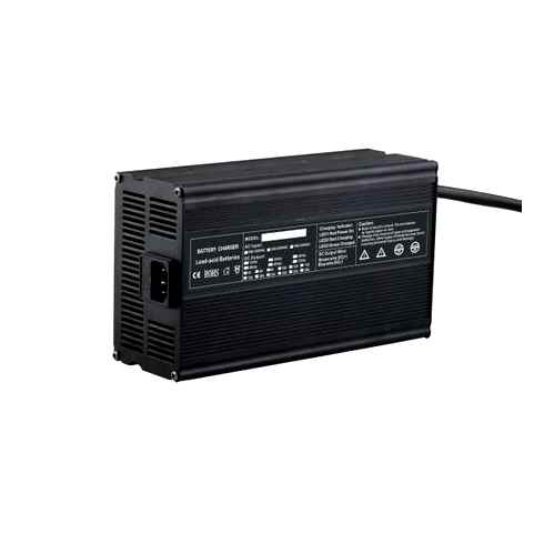
EXAMPLE CHARGING FIT E-BIKE BATTERIES WITH YOUR CAMPER CAMPER VAN
The FIT e-bike battery is an example of how you can charge an e-bike with an inverter in a camper van. The FIT BASIC CHARGER charges the FIT battery in the shortest possible time with its 4 A charging current, so that you can continue to enjoy the ride on your e-bike. If you have the appropriate infrastructure, the FIT FAST CHARGER even offers a 6 A fast charge option, which makes charging even quicker. The average charging time for a 500 Wh battery is about 3 hours, for a 630 Wh battery 3.8 hours and for a 750 Wh battery 4.5 hours.
Two formulas can be used to calculate the required capacity of the on-board battery and the required inverter power. If you want to charge two e-bike batteries with 500 Wh, for example, you should divide this by the 12 V battery voltage, include a loss of 15 % in your calculation, and thus arrive at 96 Ah. But watch out: since the battery should never be fully discharged, a reserve of around 50 % must also be factored in.
The inverter power required for our example is calculated in turn by multiplying the 4 A of the charging current by the 36 V voltage of the e-bike battery. Once again, you should allow for a loss of 15 %, resulting in a minimum output of 166 W in this case. If we assume two batteries, the inverter should be able to consistently deliver 332 watts. With calculated reserves, a 500 watt voltage transformer would be a good choice.
Required battery capacity: 1000 Wh / 12 V 15 % loss = 96 Ah
Required inverter output:4 A x 36 V 15 % loss = 166 W
TIPS FOR CHARGING E-BIKE BATTERIES EN ROUTE
Lithium-ion batteries should not be constantly discharged and fully recharged. In principle, a charging status of between 20 and 80 % is recommended if you want to preserve the battery. 2. If you want to charge the e-bike battery with the camper van’s own 12 V DC current, you will need an inverter to operate the e-bike battery charger at 230 V. 3. The inverter should be of high quality and be able to provide a true sine wave. It should also meet the minimum battery charging capacity. 4. You can charge more while driving because the alternator, ideally in combination with a charge booster, provides extra power. In this way, even large amounts of electricity can be generated from the car battery. 4. Solar power helps give you more energy reserves. You can also compensate losses from the on-board battery in this way. An output of at least 200 Wp is recommended.
You are often on the road with the e-bike? In the following blog post you will get tips on how to increase the battery range: 10 Tips for longer tours
Products
Electric Bike/Scooter Batteries
Charger
LiFePO4 RV/LEV Batteries 12V 120Ah 1. Inbuilt Military Standard BMS: It has a built-in Multi-functional 120A continuous BMS, 360A for 30 sec peak, with high-quality IC and MosFET for over-current, over-discharge, over-charge, short-circuit, adverse-polarity connection, balancing functions. 2. Wide Applications: It can be used for solar energy 1
LiFePO4 Solar Energy Storage System ESS Battery 24V100Ah LiFePO4 batteries for solar storage: Cycle stability at high current, Fast charging within 1 hour, Deep discharge protection, overcharge protection, Voltage and temperature monitoring, Single cell monitoring, State of charge determination(SOC and SOH).

LiFePO4 Marine Batteries 12V 48V 240Ah Battery Pack Custom Li-ion Marine Batteries 12V 48V 240Ah: Light weight and strong power, sell to France and Russia and gain best praise, customers show it on their website to expand markets.
LifePO4 Motorcycle Start Batteries. compared to the lead-acid batteries, they are smaller, lighter, Safer and Longer.
Electric Bike/Scooter/Rickshaw Batteries. the most welcomed batteries in abroad, equipped with Smart BMS and Bluetooth.
Lithium RV/LEV Batteries. applicable to golf-cart, sightseeing bus and caravan, we have build a great market in European countries.
Portable Power Station Batteries. small energy storage system for indoor and outdoor applications.
Solar Light Lithium Batteries like street light batteries, LFP solar light batteries.
Power Storage Batteries. cost-effective; BMS safety system that monitors and balances and optimally charges the cells.
Super long life which can use for over than 1000 times, with fashionable design so that the data is readable via UART such as voltage, current, temperature, cycles …With Bluetooth 4.0 communications for mobile devices via APP; it has the functions of Coulomb energy calculation, and FCC update functions; Cycles and alarm data record, electric bicycl1
This mutlifunctional portable UPS power station is a small energy storage system for indoor and outdoor applications, it can be used for home utility devices like electric fans and computer, with the safety insurance, stable power supply capacity and portable benefits, it deserves for your choise.
LiFePO4 batteries for solar storage: light, small and durable. Long-life lithium-ion battery 100Ah with integrated BMS, ultra safe.
Solar Light Energy Storage LifePO4 Battery:Long-lasting,maintanance-free, prolonged cycle life,competitive price,no necessary to change the battery all the time.
High density of energy, low self-discharge, low internal resistance, long lifespan, safety insurance, safest and longest lasting, 24V 52V Lithium Ebike Battery works efficiently
Superior performance, full protection, adjustable to fit in more cells, low internal resistance, environmental friendly, long period life,equipped with 48V 52V ebike battery pack
Optional Smart system, super long cycle life, full protection BMS, affordable and powerful battery cells, to your demands, we provide the configuration like 7S4P and 10S3P for you, if you want to other type, we can also desigh for you.
Premium Samsung Cells, smallest sized pack, high compatiblity, incredible range, top quality battery. reasonably priced, we choose Chinese cell XINCHI, the highest quality Panasonic cell from Japan and Samsung cell form Korea to made trustable and flexible ebike battery.
KOK POWER LIMITED (KOK), founded in 2011, is pioneer of Smart lithium-ion battery systems in China. Our Smart batteries can display monitor the batteries status and thus enable the devices to conserve and use power intelligently with a patented built-in battery management system (BMS) via blue-tooth or other communications through APP or on screen. KOK is strong in RD and manufacturing of Smart battery systems, widely used in fields such as E-mobility (e-bike, e-scooter, e-skateboard, e-motorcycle, e-tricycle/rickshaw, e-wheelchair, e-golf cart, e-forklift, e-tourist vehicle, RV/caravan,marine,etc.), Energy Storage Systems (solar/wind system, telecom/base station, uninterruptible power supply/UPS/backup system) and engine starter batteries. KOK batteries can readily replace the outdated, bulky and pollutant Lead-Acid / AGM/ GEL/SLA batteries with the latest Smart lithium battery technology. KOK staff, from senior management to direct operators, have over 8 years’ experience of building batteries for many applications.All assembling operators are trained to high standards;and our sales team are good communicators. We will work with you to find a custom power solution for your applications and will provide you with complete design, build and test solutions tailored to your specific needs. KOK has been awarded as Hi-Tech Company of Guangdong Province, and products are designed to be safe, reliable and competitively priced. All our products are designed and manufactured to the highest standards and meet or exceed industry safety and environmental standards including: ISO9001, IEC62133, UL1642 / UL2054,CE,RoHS. We have professional manufacturing as follows Our Vision: Providing battery solutions to improve the global environment Our Core Value: Developing cutting-edge battery technologies and providing all-round customer support Our Mission: Transcending customers’ expectations, and boosting customers’ growth
BU-302: Series and Parallel Battery Configurations
Batteries achieve the desired operating voltage by connecting several cells in series; each cell adds its voltage potential to derive at the total terminal voltage. Parallel connection attains higher capacity by adding up the total ampere-hour (Ah).
Some packs may consist of a combination of series and parallel connections. Laptop batteries commonly have four 3.6V Li-ion cells in series to achieve a nominal voltage 14.4V and two in parallel to boost the capacity from 2,400mAh to 4,800mAh. Such a configuration is called 4s2p, meaning four cells in series and two in parallel. Insulating foil between the cells prevents the conductive metallic skin from causing an electrical short.
Most battery chemistries lend themselves to series and parallel connection. It is important to use the same battery type with equal voltage and capacity (Ah) and never to mix different makes and sizes. A weaker cell would cause an imbalance. This is especially critical in a series configuration because a battery is only as strong as the weakest link in the chain. An analogy is a chain in which the links represent the cells of a battery connected in series (Figure 1).
| Figure 1: Comparing a battery with a chain. Chain links represent cells in series to increase voltage, doubling a link denotes parallel connection to boost current loading. |
A weak cell may not fail immediately but will get exhausted more quickly than the strong ones when on a load. On charge, the low cell fills up before the strong ones because there is less to fill and it remains in over-charge longer than the others. On discharge, the weak cell empties first and gets hammered by the stronger brothers. Cells in multi-packs must be matched, especially when used under heavy loads. (See BU-803a: Cell Mismatch, Balancing).
Single Cell Applications
The single-cell configuration is the simplest battery pack; the cell does not need matching and the protection circuit on a small Li-ion cell can be kept simple. Typical examples are mobile phones and tablets with one 3.60V Li-ion cell. Other uses of a single cell are wall clocks, which typically use a 1.5V alkaline cell, wristwatches and memory backup, most of which are very low power applications.
The nominal cell voltage for a nickel-based battery is 1.2V, alkaline is 1.5V; silver-oxide is 1.6V and lead acid is 2.0V. Primary lithium batteries range between 3.0V and 3.9V. Li-ion is 3.6V; Li-phosphate is 3.2V and Li-titanate is 2.4V.
Li-manganese and other lithium-based systems often use cell voltages of 3.7V and higher. This has less to do with chemistry than promoting a higher watt-hour (Wh), which is made possible with a higher voltage. The argument goes that a low internal cell resistance keeps the voltage high under load. For operational purposes these cells go as 3.6V candidates. (See BU-303 Confusion with Voltages)
Series Connection
Portable equipment needing higher voltages use battery packs with two or more cells connected in series. Figure 2 shows a battery pack with four 3.6V Li-ion cells in series, also known as 4S, to produce 14.4V nominal. In comparison, a six-cell lead acid string with 2V/cell will generate 12V, and four alkaline with 1.5V/cell will give 6V.
If you need an odd voltage of, say, 9.50 volts, connect five lead acid, eight NiMH or NiCd, or three Li-ion in series. The end battery voltage does not need to be exact as long as it is higher than what the device specifies. A 12V supply might work in lieu of 9.50V. Most battery-operated devices can tolerate some over-voltage; the end-of-discharge voltage must be respected, however.
High voltage batteries keep the conductor size small. Cordless power tools run on 12V and 18V batteries; high-end models use 24V and 36V. Most e-bikes come with 36V Li-ion, some are 48V. The car industry wanted to increase the starter battery from 12V (14V) to 36V, better known as 42V, by placing 18 lead acid cells in series. Logistics of changing the electrical components and arcing problems on mechanical switches derailed the move.
Some mild hybrid cars run on 48V Li-ion and use DC-DC conversion to 12V for the electrical system. Starting the engine is often done by a separate 12V lead acid battery. Early hybrid cars ran on a 148V battery; electric vehicles are typically 450–500V. Such a battery needs more than 100 Li-ion cells connected in series.
High-voltage batteries require careful cell matching, especially when drawing heavy loads or when operating at cold temperatures. With multiple cells connected in a string, the possibility of one cell failing is real and this would cause a failure. To prevent this from happening, a solid state switch in some large packs bypasses the failing cell to allow continued current flow, albeit at a lower string voltage.
Cell matching is a challenge when replacing a faulty cell in an aging pack. A new cell has a higher capacity than the others, causing an imbalance. Welded construction adds to the complexity of the repair, and this is why battery packs are commonly replaced as a unit.
High-voltage batteries in electric vehicles, in which a full replacement would be prohibitive, divide the pack into modules, each consisting of a specific number of cells. If one cell fails, only the affected module is replaced. A slight imbalance might occur if the new module is fitted with new cells. (See BU-910: How to Repair a Battery Pack)
Figure 3 illustrates a battery pack in which “cell 3” produces only 2.8V instead of the full nominal 3.6V. With depressed operating voltage, this battery reaches the end-of-discharge point sooner than a normal pack. The voltage collapses and the device turns off with a “Low Battery” message.
Batteries in drones and remote controls for hobbyist requiring high load current often exhibit an unexpected voltage drop if one cell in a string is weak. Drawing maximum current stresses frail cells, leading to a possible crash. Reading the voltage after a charge does not identify this anomaly; examining the cell-balance or checking the capacity with a battery analyzer will.
Tapping into a Series String
There is a common practice to tap into the series string of a lead acid array to obtain a lower voltage. Heavy duty equipment running on a 24V battery bank may need a 12V supply for an auxiliary operation and this voltage is conveniently available at the half-way point.
Tapping is not recommended because it creates a cell imbalance as one side of the battery bank is loaded more than the other. Unless the disparity can be corrected by a special charger, the side effect is a shorter battery life. Here is why:
When charging an imbalanced lead acid battery bank with a regular charger, the undercharged section tends to develop sulfation as the cells never receive a full charge. The high voltage section of the battery that does not receive the extra load tends to get overcharged and this leads to corrosion and loss of water due to gassing. Please note that the charger charging the entire string looks at the average voltage and terminates the charge accordingly.
Tapping is also common on Li-ion and nickel-based batteries and the results are similar to lead acid: reduced cycle life. (See BU-803a: Cell Matching and Balancing) Newer devices use a DC-DC converter to deliver the correct voltage. Electric and hybrid vehicles, alternatively, use a separate low-voltage battery for the auxiliary system.
Parallel Connection
If higher currents are needed and larger cells are not available or do not fit the design constraint, one or more cells can be connected in parallel. Most battery chemistries allow parallel configurations with little side effect. Figure 4 illustrates four cells connected in parallel in a P4 arrangement. The nominal voltage of the illustrated pack remains at 3.60V, but the capacity (Ah) and runtime are increased fourfold.
A cell that develops high resistance or opens is less critical in a parallel circuit than in a series configuration, but a failing cell will reduce the total load capability. It’s like an engine only firing on three cylinders instead of on all four. An electrical short, on the other hand, is more serious as the faulty cell drains energy from the other cells, causing a fire hazard. Most so-called electrical shorts are mild and manifest themselves as elevated self-discharge.
A total short can occur through reverse polarization or dendrite growth. Large packs often include a fuse that disconnects the failing cell from the parallel circuit if it were to short. Figure 5 illustrates a parallel configuration with one faulty cell.
A weak cell will not affect the voltage but provide a low runtime due to reduced capacity. A shorted cell could cause excessive heat and become a fire hazard. On larger packs a fuse prevents high current by isolating the cell.
Series/parallel Connection
The series/parallel configuration shown in Figure 6 enables design flexibility and achieves the desired voltage and current ratings with a standard cell size. The total power is the sum of voltage times current; a 3.6V (nominal) cell multiplied by 3,400mAh produces 12.24Wh. Four 18650 Energy Cells of 3,400mAh each can be connected in series and parallel as shown to get 7.2V nominal and a total of 48.96Wh. A combination with 8 cells would produce 97.92Wh, the allowable limit for carry on an aircraft or shipped without Class 9 hazardous material. (See BU-704a: Shipping Lithium-based Batteries by Air) The slim cell allows flexible pack design but a protection circuit is needed.
Li-ion lends itself well to series/parallel configurations but the cells need monitoring to stay within voltage and current limits. Integrated circuits (ICs) for various cell combinations are available to supervise up to 13 Li-ion cells. Larger packs need custom circuits, and this applies to e-bike batteries, hybrid cars and the Tesla Model 85 that devours over 7000 18650 cells to make up the 90kWh pack.
Terminology to describe Series and Parallel Connection
The battery industry specifies the number of cells in series first, followed by the cells placed in parallel. An example is 2s2p. With Li-ion, the parallel strings are always made first; the completed parallel units are then placed in series. Li-ion is a voltage based system that lends itself well for parallel formation. Combining several cells into a parallel and then adding the units serially reduces complexity in terms of voltages control for pack protection.
Building series strings first and then placing them in in parallel may be more common with NiCd packs to satisfy the chemical shuttle mechanism that balances charge at the top of charge. “2s2p” is common; white papers have been issued that refer to 2p2s when a serial string is paralleled.
Safety devices in Series and Parallel Connection
Positive Temperature Coefficient Switches (PTC) and Charge Interrupt Devices (CID) protect the battery from overcurrent and excessive pressure. While recommended for safety in a smaller 2- or 3-cell pack with serial and parallel configuration, these protection devices are often being omitted in larger multi-cell batteries, such as those for power tool. The PTC and CID work as expected to switch of the cell on excessive current and internal cell pressure; however the shutdown occurs in cascade format. While some cells may go offline early, the load current causes excess current on the remaining cells. Such overload condition could lead to a thermal runaway before the remaining safety devices activate.
Some cells have built-in PCT and CID; these protection devices can also be added retroactively. The design engineer must be aware than any safety device is subject to failure. In addition, the PTC induces a small internal resistance that reduces the load current. (See also BU-304b: Making Lithium-ion Safe)
Simple Guidelines for Using Household Primary Batteries
- Keep the battery contacts clean. A four-cell configuration has eight contacts and each contact adds resistance (cell to holder and holder to next cell).
- Never mix batteries; replace all cells when weak. The overall performance is only as good as the weakest link in the chain.
- Observe polarity. A reversed cell subtracts rather than adds to the cell voltage.
- Remove batteries from the equipment when no longer in use to prevent leakage and corrosion. This is especially important with zinc-carbon primary cells.
- Do not store loose cells in a metal box. Place individual cells in small plastic bags to prevent an electrical short. Do not carry loose cells in your s.
- Keep batteries away from small children. In addition to being a choking hazard, the current-flow of the battery can ulcerate the stomach wall if swallowed. The battery can also rupture and cause poisoning. (See BU-703: Health Concerns with Batteries)
- Do not recharge non-rechargeable batteries; hydrogen buildup can lead to an explosion. Perform experimental charging only under supervision.
Simple Guidelines for Using Secondary Batteries
- Observe polarity when charging a secondary cell. Reversed polarity can cause an electrical short, leading to a hazardous condition.
- Remove fully charged batteries from the charger. A consumer charger may not apply the correct trickle charge when fully charged and the cell can overheat.
- Charge only at room temperature.
References
[1] Courtesy of Cadex
The material on Battery University is based on the indispensable new 4th edition of “Batteries in a Portable World. A Handbook on Rechargeable Batteries for Non-Engineers” which is available for order through Amazon.com.
Комментарии и мнения владельцев
Комментарии и мнения владельцев are intended for “commenting,” an open discussion amongst site visitors. Battery University monitors the Комментарии и мнения владельцев and understands the importance of expressing perspectives and opinions in a shared forum. However, all communication must be done with the use of appropriate language and the avoidance of spam and discrimination.
If you have a suggestion or would like to report an error, please use the “contact us” form or email us at: BatteryU@cadex.com. We like to hear from you but we cannot answer all inquiries. We recommend posting your question in the comment sections for the Battery University Group (BUG) to share.
I’m having trouble and was hoping you could help me. I have (2) JY Power HP-40s in my vehicle. They’re connected together using aluminum bars At resting the voltage on both is 13 volts (approximately). Once I start the vehicle 1 jumps immediately to 14.7 (approximately) and the other stays at resting. When I turn the stereo system on, I can watch the battery monitor (wired in to each battery) on the battery at 14.7 fluctuate from pulling power. The battery that sits at resting does not fluctuate. I’ve double and triple checked everything and I’m at a huge stand still. Please help. Thanks in advance.
As u have shown the battery connection but would like to ask you that if we want to make a circuit for 6v 3A solar
hai sir, i have a doubt about 18650 3.7v batteries in 7 x 3 position One side both positive and negative two line short.another side oppsite line two sides shorted, WHY? pls answer me sir thankyou
A circuit consists of 2 series connected batteries; the positive terminals of the batteries are connected to each other; the negative terminals connects the rest of the circuit. One battery is rated 100V and the other, 350V. This series connection is further connected to a single series load resistor. After connecting the load resistor, a potential difference of 228,7 V was observed across the load. A current of 15,25 A was measured. Determine the internal resistance values of the batteries if the volt drop in the 100V cell is 10.7V.
In Figure 6 above, if I have a NiCd cell batteries, which configuration is better, series all cells then parallel or parallel both then connect in series. Meaning in between cell there is no jumper to parallel two cell or batt. It’s like 2s then parallel as compared to 2p then series it.
The nominal cell voltage for a nickel-based Hi. I had the understanding earlier on that Li-ion are of many types including Li-posphate, Li-cobalt etc but this statement in the sixth paragraph seems to suggest that Li-ion isn’t a name for a group of batteries but is a specific battery chemistry “Primary lithium batteries range between 3.0V and 3.9V. Li-ion is 3.6V; Li-phosphate is 3.2V and Li-titanate is 2.4V.”
How48V,20AH lead acid battery can replace 60V,24AH LiFePO4 battery.
The nomenclature proposed above is not optimal. A better system is to place the first connection first, and the second connection second. For example: 4P16S is a pack such that cells are connected in groups of 4 in parallel, and 16 of those groups are connected in series. 16S4P is a pack such that cells are connected in groups of 16 in series, and 4 of those groups are connected in parallel.
Also, using an example of 4S4P is ambiguous. It would be better to use unequal values of S and P to clearly illustrate the point.
Looking at all this explanation I gained more knowledge and skills and experience how to connect my solar to a battery.
OK, this new format looks better. Will we be able to see the Комментарии и мнения владельцев from 2019-2021, please? Regards,
Looking for Комментарии и мнения владельцев from the previous website?
Комментарии и мнения владельцев from the previous website are not compatible with our new commenting system but we have preserved them so our users can still reference and make use the information in them.
Does single battery (e.g, LA, SLA, L-ion) better or multiple battery (in parallel) with same capacity (same AH) is better?
The free Android app “Battery Package Calculator” can help you calculate the parameters of battery packets.(up to 9999s 9999p) 🙂 https://play.google.com/store/apps/details?ID=pl.freshdata.batterypackagecalculator
I want to make a battery with 26650,500mah. I need 14.8v. How would I make a 4s 2p. I see the drawing for the 2s 2p. But you can say I am slow. Thank You for your help and time
how to best connection in power bank (Series Connection cell or Parallel Connection cell) Kindly write easy answer!
i want to 60 v 25 Ah battery pack by using 3.7 v 2.2 A lithium ion cells. how can i connect them to get better efficiency. is their any better way to connect them. i mean S ans P connection tricks
For an electric vehicle, I am looking at Nissan Leaf Gen 2 batteries. I am planning to use 48 Leaf modules at 8v and 66 ah. If I put the all in series, I will get 384v and 66 ah, I think. If I want more current, I go with 45 modules is series and 3 in parallel, do I get 360v and 198 ah or do I lose something along the way? John
I have a LiitoKala Lii-402 battery charger. The input is labeled 5V2A. How is this thing able to charge 4 3.7V Li-ion batteries in just a few hours? I purchased a BMS charger that wants something like 15V input to charge the same 4 batteries.
Hi Guys and Girls Could someone clarify for me the best configuration for an 18 x 48100ah Shoto Lithium Ion Battery Setup please? 3 Cabinets each with 6 units is what we’re looking at. Are there any suggestions regarding the monitoring softwares? Any extra Inforation would be highly appreciated. THANKS!
I have 4 3.2v 18650 batteries connected in series to power a 12v motor. Can I make a second 6v output from 2 of those 4 batteries and power both the motor off the 12v and say an Arduino off the 6v simultaneously?
Dear Sir need your guidance for sourcing of simultaneous charging and discharging controlling device for battery in electric vehicle Regards C.A.Nemade
Dear Sir Thanks for your Quick response and useful information Surely with your information I can able to take a step forward towards green energy I will surely disturb you If any further information is required. Regards C.A.Nemade
@ CA Popular 50A 12V / 24V / 36V / 48V MPPT Solar Charge Controller.-Foshan Top One Power Technology Co., Ltd. https://oneinverter.en.made-in-china.com/product/XyAELYzcYeVU/China-Popular-50A-12V-24V-36V-48V-MPPT-Solar-Charge-Controller.html 60 AMP Solar MPPT Charge Controllers for LiFePO4 Battery.-Wenzhou Xihe Electric Co., Ltd. https://xihe-solar.en.made-in-china.com/product/BSKELQWwMNhv/China-60-AMP-Solar-MPPT-Charge-Controllers-for-LiFePO4-Battery.html Search Made in China https://www.made-in-china.com /productdirectory.do?word=48V,30ampMPPTchargecontrollersubaction=huntstyle=bmode=andcode=0comProvince=nolimitorder=0isOpenCorrection=1 These are 2 of Chians biggest solar gear manufactuerers. Huge is sizebut still supply a 1 only quanties, as opposed to others who need FCL
Dear Sir I am working on the project of @ 1000 km running of vehicle with single charge pls let me know the commercial availability of 48 V, 30 amp MPPT charge controller for combination of Lithium iron Batteries/Life4 Batteries and Generator/solar combination Regards C.A.Nemade
I have a selection of 18650 cells all around 2100ah I want to make a pack at 12 volts at 10000ah for my scooter project my question is how many cells and in what configuration 3s means a nominal 10 volts so i am thinking going 4s is a better option so how many for a 3s 10000ah and how many for a 4s 10000ah
@ Dwight here are some charger manufacturers drop them aline about batteries https://danlcharger.en.made-in-china.com/product/lvCnLHgjYzRE/China-84-Volts-14-AMPS-Smart-Battery-Charger-1500W-Suit-for-Li-ion-and-LiFePO4-Battery-Types.html for a better quality suit in-built app https://danlcharger.en.made-in-china.com/product/YBNJxahdvLUQ/China-Waterproof-Battery-Charger-72V-15A-Worldwide-110-230VAC-with-Pfc.html cheers robb
Hello I have connected 5 numbers of 3.7 V, 3400mAh 18650 batteries in parallel to get 17000 mAh battery capacity. I’m measuring more than 10 A from the output of parallelly connected batteries. I need to know is that normal? Thank you for your reply.
Thanks for the response and I do not have any heave draw only a new Samsung inverter fridge. cooking with Gas and no Aircon or heaters needed only some power tools like grinders and small drill. mainly use for lights TV internet ans cable. I am creating a sample system to run TV, Internet, Cable TV and maybe microwave and toaster. I will start with 4 (maybe 6) Trojan 8V 170AH each from Golf Carts, set up as 2S groups then 2P to get 16V and 340AH. and maybe about 300 Watt Mono PV. then I will increase the batteries and the PV step by step until I get the best performance. I have a 3000/6000 Watt inverter to start. Step 2 will be 3S groups to get 24V then 3P to get 510 AH. will see. Thanks for your help good advice
@ Ceasar You dont actually say the max draw/demand. Rule of thumb double it !12V is good forrunning a couple of leds and a phone chargerbut if you want to be able to boil the billy in the morning you will want 6x800AH in 2 banks. I know as I was sold a12V sys years ago Disadvantages of lowvoltagestorage 1. enormous cables 90mm sq 2, 20:1 transformer windings =20Amp in gives less than 1 amp out 3. loss of conversion during charging and huge heat build up Suggest using 48V min even then look @ 420AH PoV expensive but last years verycommon and proven AVOID car batteries they are woftam (WASTE OF TIME AND FUXXXING MONEY) Also suggest a split sys,,get a 2nd Hand roof top upgrade with Grid tie in and use this as you DAYSHIFT Freezer,and high draw 240V.Build a skeleton 48Vsys for night shift Hope this helps @Robert You have the perfect WOFTAM, and a perfect recipe for failure and heartbreak Tell us a bit more about this common bus. it sounds more than the negative rail. one Band aide approach would be to have each battery with its own dedicated charging system and standalone discharge system Might look like Dr Who and the inside of the T.A.R.D.I.S. but it might just work Many Public Utilities cast out 2nd hand batteries once they reach 3 years oldbut they still have a 8/10 years ahead.this is a cheap option if the PRICE is RIGHT i.e., below 30% of new price robbo
I have several batteries in a bank, all different producing 12 volts. They are different ages and amp hour rated. If I take each battery to a common buss, will that cure the problems described with multiple batteries in parallel
Hi, I am building a solar system for my home and I wonder what will be the best way to obtain the most efficient system. I use many home appliances but initially I only have some basic ones like digital Samsung fridge, toaster microwave TV internet and cable (No heater or air conditioner). so If I set my batteries in series I will only increase the voltage but I think I will be much better to maintain the 12 volts and increase the Watts Hour by setting all in parallel that way I can maintain better use of the power. Am I correct with my assumption. Appreciate your help By the way my batteries are Trojan Deep cycle at 170WH Thanks a lot Cesar
Hi, I am building a solar system for my home and I wonder what will be the best way to obtain the most efficient system. I use many home appliances but initially I only have some basic ones like digital Samsung fridge, toaster microwave TV internet and cable (No heater or air conditioner). so If I set my batteries in series I will only increase the voltage but I think I will be much better to maintain the 12 volts and increase the Watts Hour by setting all in parallel that way I can maintain better use of the power. Am I correct with my assumption. Appreciate your help By the way my batteries are Trojan Deep cycle at 170WH Thanks a lot Cesar
long old thread. but one recurring question in led acid batteries regular flooded,deep cycle type. when using multiple they need to be same age,capacity and type for best results. series to increase voltage parallel for capacity. and more than 4 batteries theirs better ways than just for example 3x 12 series then 3 in series joined parallel than just and. search hooking up many 6 or 12 v batteries simple wiring change keeps batteries balanced. and banks of flooded cells need balancing every so often. lithium cells especially large amounts need a bms system and a way to fuse remember too lead acid 50% max lithium 70% usage and read more than 1 article
ANTIQUE ELECTRIC CAR I own a 1919 Milburn Electric car and would like to purchase lithium LIFePO4 batteries instead of the using the original lead acid batteries. The motor is a 76 volt 33amp DC GE motor from the era. The original system voltage was 84 volts (42 cells in 2 modules or 21 cells each) The manual controller with 12 brass contact fingers is organized as follows : “gear” 1 slowest speed, wheels beginning to turn, most ‘torque’ the motor is energized at 42 volts with the 2 modules in parallel and a resistor in place “Gear” 2 slightly faster and ‘torque’ still required to gain speed The motor is energized at 42 volts with the 2 modules in parallel and less resistance “Gear” 3 medium speed The motor is energized at 84 voltswith the 2 modules in series and even less resistance “Gear” 4 high speed least amount of ‘torque’ The motor is energized at 84 volts with the 2 modules in series and no resistors In “off” mode the lead acid cells were placed in series and the charger provided 84 volts. I have been talking to a lithium cell supplier who is willing to supply sufficient LIFePO4 120amp cells in 2 seperate and equal modules to provide nominally 42 volts each and a BMS for each These modules are recommended to be wired in series only for 84 volts and that they stay that way He does not recommend that they be connected alternately in parallel for 42 volts 240 amps. I am assuming that there is a concern that the 2 lithium ion modules will become out of balance with each other and risk fire and explosion A consistent 84 volt system will not work in this car Any suggestions that would lead to successful usage of lithium cells in 2 equal but separate 42 volt modules? Thank you
Hello All. I have 14 batteries 1.2V 4000mAh NiMh connected in series to get 16.8V pack. the pack has one PCB which i think to protect the batteries during the charging and usage. is there ready made similar PCB as mine is damaged and need to replace it. any advise on best way to overcome this.
Hello I have a battery/inverter set up in my garage comprising the following items. 1) One 5kVA RCT-axpert inverter, 48 VDC input, 220 VAC out. 2) 16 X 105 A/H, 12V Enertec Deep Cycle silver calcium batteries. Configured in 4 parallel banks of 4 batteries in series. These were installed about 3 years ago. This morning, I noticed a strong pungent smell in the garage area and found that one of the battery bank string was extremely hot which prompted me to disconnect it immediately. I suspect that one batteries in the hot bank could have developed an internal short. The batteries are constantly on maintenance.trickle charge, as provided by the inverter. Could you provide an opinion concerning this overheating incident. Thank you
do batteries (ie 12 v) have to be the same CCA when used in parallel for instance using a 500 CCA battery with a 875 CCA battery?
I have 6 (18650) li-ion batteries that i want to use for lead acid replacement for my motorcycle. Can i connect 3in Series and 3 in Parallel to achieve 14.4V ? How do i connect the 3inSeries with 3in Parallel onto each other and how to use a BMS for this configuration?My plan is to use this lithium pack to keep a pack of 6 supercapacitors always charged
Has anyone tried out a hydralight fuel cell? salt and water powered battery? Wondering if they would make a good solution for setting them up with many cells to power a house in a no power post hurricane emergency situation. Also wondering if anyone has tested them side by side with a normal d-sized 1.5 volt flashlight battery to see which lasts longer.
I plan to use two 12V 100aH batteries connected in series to create a 24V 100aH battery bank to power a 24V inverter. The bank will be charged by a 24V solar charge controller. 1. Do both batteries in the series configuration discharge at the same rate? Or does the upper battery discharge first and then the lower battery? 2. Will the 24V charge controller charge both batteries back up to their full charge? Or do I need to have two separate 12V controllers, one on each battery, in order to get both fully charged?
Can you reduce DC Ampere using resistors? serial or parallel. eg. (12V 11Ah DC) Resistor (OUTPUT 12V 1AhDC)
Hii, I have 24V battery system Two lithium-ion batteries connected in series connected to a Smart charger and inverter system. The batteries have a BMS of their own whose data can be accessed through Bluetooth. There are some DC loads on the battery system running on 24V. Now I charged both the batteries(in series) till 100% ( checked from BMS of both of them) and then started discharging the system. Today when I checked, one of the batteries were at 68% and another one at 94%. Both had the same discharging current and voltage as per BMS. So my question is what could be the reason behind unequal discharge. Both the batteries are new, same brand, same capacity. has anyone seen similar cases before.
I have a main circuit board in a machine that over a year or two eventually drains a 3.6v lithium AA size down to 1.4V. This battery has a wire soldered at each end which is then soldered to two points on the circuit board and is used to maintain data when the machine is shut down so it is there upon startup. I would like to use a parallel 4 battery holder that connects by soldering directly to the main board in place of the single battery and that the batteries can be removed from individually and easily without having to deal with soldering. My reason for this is that if the battery voltage drops down to the point that the machine no longer retains data then it takes about a half hour to reprogram the machine after changing (unsoldering and resoldering) the battery. I am hoping that by having multiple batteries in parallel they can be removed one at a time and be replaced without worrying about loss of data since it is still providing enough voltage. My concern is what I don’t know, which is if there are any adverse effects of having more than one battery even if in parallel. The battery I will use four or at least more than one if there are no problems is SAFT LS14500 Size AA 3.6V 2600mAh Primary Lithium (Li-SOCl2) Battery. This is the same type of battery that is wired singly to the circuit board now. I appreciate the help of those that are much more knowledgeable about this than me.
Hello, Could you please offer some advice. I’d like to know if there is a single cell battery that would be equivalent in size and voltage to a series stack-up of 4x AG3. I’d much prefer a single cell rather than fussing with four tiny batteries. Thank you.
@ Karl Series is the only way to charge batteries over an extended period. I have tried all sorts of ways to charge 12V batteries in parallel and long story short it is a waste of time. Often one battery is dead flat and others fully charged and are drawn down to the lowest voltage If you have GOOD batteries hook them in series and buy a new inverter of that voltage I did have a 6kw 12 V inverter (transformer type) running of 6x800Ah 2vPoe Batteries it worked well and could boil an electric jug in the morning Go series Robbo
I have a homemade solar setup. I use 4 identical 12 volt deep cycle marine batteries in parallel to power the inverter. I want to add capacity. I understand that it is important to use the same type of battery. Can I safely add 2 more batteries? Can I add 4 more? Is there a limit to how many batteries I can safely wire in parallel? Thank you in advance for your help.
@ Theo I have a mobility scooter powered with 3 AGM batteries 12v 28 ah, I can do only 10 to 12 Km. I live in a hilly suburb, if I want more distance and be prepared to buy an additional 3 batteries, of say 80 ah each so when I run out of power I can switch to the other bank. Could you please give me some advice how to connect those aditional batteries to get the required 70a for my scooter controller and have more distance I require to visit my local shopping centre, I don’t need speed just the wire connection of the 3 batteries to get the most ah. Hello Theo the math says it all, Your scooter draws 70 amp and you batteries supplies a total of 84 a/h, or just over one hour @ peak. Installing 3 x 80a/h would supply 240a/h or nearly 3 times the capacity and distance. If you install a second sett of batteries you would need a charging splittter as used in 4WD with twin batteries and a battery switch for A B banks (it gets complicated ) so stick with the new80a/h batteries
How do I get that information I ask for in my recent email of April 27 2018? Thank you, Theo Veeren veerent@bigpond.com
Hello to whoever reads, I need a low self-discharge battery (Lithium Thionyl Chloride) to power a microcontroller (somewhat like Arduino). It can handle 3.9. 12V and needs about 1800mA current in pulses. The Li-SOCl2 batteries I’ve been looking at is at 3.6V with 35000mAh capacity and can give a maximum continuous current of 450mA. If I put 2 of these batteries in parallel would I get twice the maximum continuous current (900mA) as the capacity also becomes twice the size? Sorry if this is a stupid question, but i’d rather find out here than to spend a bunch of money and realize it doesn’t work 😉 Thanks in advance, Michael
Hi.Sir/Madam I have a mobility scooter powered with 3 AGM batteries 12v 28 ah, I can do only 10 to 12 Km. I live in a hilly suburb, if I want more distance and be prepared to buy an additional 3 batteries, of say 80 ah each so when I run out of power I can switch to the other bank. Could you please give me some advice how to connect those aditional batteries to get the required 70a for my scooter controller and have more distance I require to visit my local shopping centre, I don’t need speed just the wire connection of the 3 batteries to get the most ah. Thank you. Theo,
For the Series/Parallel Connection, I don’t think the math adds up. If Figure 6 has 2 cells in series and its voltage doubles, and 2 series connections in parallel so its amperage doubles, then how does the Energy of four cells come out to 12.24 Wh? By my math: 3.6V 2 cells = 7.2 V; 3400mAh 2 = 6800 mAh; Power = Voltage Current = 7.2V 6800mAh = 48.96Wh
Hi Lior 10 x12Vdc = 120VDC @100A 12000W which is a good overnight storage to run a small house and one/two freezers. about the same size as a small Tesla battery It wont store enough for high load AC or huge heaters but but will run them for a few hours as needed U should still be able to boil the kettle in the morning Look on the web for an inverter 120VDC to 110/220V 5KVa or better and hook 20 x 300w @36V to give 5kw charge @150VDC to your inverter. Go series NOT 12V parallel Rule of thumb is panels should have a voltage about 25% above the battery bank voltage. Battery capacity is normal 2.5 /4.0 times the rated output of cells Solar is a necessity batteries are a luxury Batteries cost the money more so than panels PS if U dont want the batteries send them here, plenty of panels batteries hard to find and expensive still robbo
@ djay wrote: I need your help. I have 8, 6 volts, 450 amps battery. I need to get 48 volts and 450 amps or 950 amps. please help me with the wiring. Hi Djay its simple maths 8 batteries @ 6Vdc =48 Vdc connected in series positive to negative Wire sizes should be proportioned according to load 90sqm cables or (super duty welding leads would suffice @ 450A and doubled for 900amps You 8s2p or another 8 batteries to get 900A. What is the end use. the batteries would only have an intermittent discharge before overheating.~5/10% on cycle 90/95off cycle Use tinned welding cable that is soft and pliable, with professional crimps or soldered ends. Apply silicone grease to poles and conducting surfaces of lugs. Tension to recommended torque and check often, as they “hum” of this high discharge rate will shake and vibrate leads loosening the bolts/lugs. Thats a lot of power and if needed continuously a1200A Lincoln Sub Arc welder feeding from a 125A 415V Nelson Studs are spot welded onto bridge deck beams using a pulse welder with programmable amps and time and produce 2000amps Oddly they have 1 x 90sqmm positive lead and 4 x 90sqmm earth leads. the whole machine runs red hot and the leads are often seen smoking They use big rivet looking studs to 25mm dia in a gun with a cermic ring that holds the instant arc and molten metal in place drop the stud end into this molten bath until it solidifies Takes about 5 seconds as opposed to 6 x 4.00mm welding rods to give the same fillet size Gutsy machines but need a 250A 415V feed and or stand alone transformer
Hello I have a home solar system and I have two solar panels of 300W and my system is 24V. In addition I have 10 batteries of 12V and 100A each battery. I wanted to ask how to connect my panels to MPPT which means plug them into 36V or 72V? I want to use most of the electricity at night Thank you
I need your help. I have 8, 6 volts, 450 amps battery. I need to get 48 volts and 450 amps or 950 amps. please help me with the wiring.
@faizan Go to ebay there are dozens available for under 20US Here is one that may be veery useful as it is bare bones (you can easily see how it works and get an understanding) Also included are a single 18650 battery holder, a USB lead, and a phone charger lead. These alone would cost more to buy at the corner store if sold seperate Chimole 3.5W 5V Solar Panel Charging For 18650 Rechargeable BatterySolar Cell power bank Portable solar charger for Smart watch https://www.aliexpress.com/item/3-5W-5V-Solar-Panel-Charging-For-18650-Rechargeable-Battery-Solar-Cell-power-bank-Portable/32812373464.html?src=googlealbslr=225178492isdl=yaff_short_key=UneMJZVf&source;=src=googlealbch=shoppingacnt=494-037-6276isdl=yalbcp=1001718710albag=52375743834&slnk;=trgt=349475913279&plac;=crea=en32812373464netw=gdevice=c&mtctp;=gclid=EAIaIQobChMIzNSg7bK42QIVxwgqCh1WvwTgEAQYASABEgK0WPD_BwE It isalso available for under12.00 from https://www.banggood.com/3_5W-5V-130165mm-Solar-Panels-Charge-With-18650-Battery-Case-p-1167475.html?gmcCountry=AUcurrency=AUDcreateTmp=1utm_source=googleshoppingutm_medium=cpc_elcutm_content=zouzouutm_campaign=pla-au-ele-acs-dk-pcgclid=EAIaIQobChMIvMTPqLu42QIVV4C9Ch36zwF_EAQYASABEgKOv_D_BwEcur_warehouse=CN You can still tell your freinds you put it together The other option is to get some chips 7809, op amps,comparator chip,a timer, make a circuit board,install resistors and caps,solder on the headers, make the boxes and viola. 6monts later after hundreds of hours tinkering you either have something that works or a load of shite that ends up in the bin! Thats life. itsuptuyu. Remember, the poor man pays twice Cheers robbo
Hi! I had a small 9V solar system with a battery bank. I am using two 18650 batteries in series and they are being charged by solar panel and also gives back up power to my device which needs 6V 110mA atleast. But, after couple of hours of running second battery goes dead while first battery remains ok. and also solar panel does not produce enough voltage either where as it should be producing. what could be the problem? can anyone tell me? batteries can last about one and half day on full charge but they just gone bad. infact second one gone bad totally then the first one. Please help me
@Yujin An Per my last comment, I left out charge time details. Technically you might be able to charge 28 coin cells faster than a larger single cell, but at a cost of complexity and balancing issues (don’t expect it to last long as a power pack). Furthermore, 28 coin cells would be like 90cm x 5.8cm, whereas an 18650 is 18mm x 65mm and a 26650 is the same length but 26mm wide. I think this is about the best you can do, and it’s my recommendation to either use 18650 or 26650 cells, but make sure your gauge wire can handle the amps without getting hot: 26650 Specs: 3.7v @ 5.2 Ah = 19.98wH 5v @ 3 Amps (assuming discharge of ~50%) = ~40 minute charge 18650 Specs: 3.7v @ 3.0 Ah = 11 wH 5v @ 3 Amps (assuming discharge of ~50%) = ~23 minute charge Please note that actual charge time may vary, but this is an estimate based on capacity. Hope that helps and send you on the right direction. Thanks
@Yujin An I guess my last response was lost or something. I’ll keep it simple though. you might want to consider using 26650 cells instead. it be smaller than 28 coin cells and way less complicated. 1x would offer 3.7v at ~5Ah already. Not an endorsement, but I’d recommend EBL brand for the price and reliability. I’d imagine it cost less too, there’s no parallel/series charge issues and would require no BMS technically, etc. Best of luck!
I have three batteries use in my 4 wheel robot.I have 4 dc 200 rpm 12v motor. and I connect 6v 4.5 ah two batteries in series connect ed and it’s parallel connect one 12 v 1.3 battery. when switch on then my robot is not a full running. it’s torque and speed both very less. I don’t know what is reason. plyz reply me for this solution. tq
really helpful article! Can u help me. I’m student in mechanics. so I don’t know well about the battery and else things. I have some question for u. I want to charge lithium ion battery pack (28 coin cells of 3.5Ah, 3.7V and configuration is 471 = TWL ) than how to cinfigurate the circuits of charging. I have to charge in 30 minutes. 🙁
Great article, there’s a lot of information out there that’s just confusion because they don’t read in plain English. The illustrations/diagrams were also very helpful to visualize the parallel vs series circuits and helps to visualize and realize the benefits of a hybrid system. I just wanted to leave a comment and say I wish I came across more information written this way and I’ll use this article to educate my son. Thanks a bunch! Micheal
Daniel wrote: I have 4x 12v AGM battery connected in series for a total of 48V. I would like to be able to switch off the circuit using a 12V 30A switch. How much voltage would be accross that switch in the off/on position if I was to install it between the first battery and second battery. ? Is it possible at all? Daniel Volts can be cosidered as pressure (in a hydraulic system) a 12 v hasless insulation than a 48V switch or solenoid have a look here at the main circuit breakers as used golf carts follow the link below. Most trucks use the ignition key to activate a HD solenoid and a loud thunk can be heard when the solenoid engages. They are commonly called 4 wire i.e., 2 wires for power and 2 wire to activate. IMHO connect the switch at the 48V terminal Golf Cart Solenoid | eBay www.ebay.com/bhp/golf-cart-solenoid 48 Volt Golf Cart Pre-Charge Solenoid Resistor | For 48 Volt 400 Amp Solenoids. 8.50. Buy It Now. DC Battery Disconnect Switches. WhisperPower www.whisperpower.com/au/4/24/products/battery-switches.html
I have 4x 12v AGM battery connected in series for a total of 48V. I would like to be able to switch off the circuit using a 12V 30A switch. How much voltage would be accross that switch in the off/on position if I was to install it between the first battery and second battery. ? Is it possible at all? Switch. Load.
can i connect two batteries having different voltages in parallel and connected with opposite terminals
Lucas buzek wrote: I am trying to figure a solution for my problem. Connecting 8 12V batteries for 24V charge and dual 24V and 96V outputs. Would diodes on the terminals of each battery cell be sufficient to prevent short circuit? Current configuration is 4 batteries connected in parallel for higher capacity and then connected in series for 24V charge and output. And I’m thinking of adding another layer of wiring to connect all 8 batteries in series (with one-way diodes to prevent short circuits) to achieve 96V output. Is something like this possible or should I just use a voltage booster? Lucas The first problem to overcome is how to charge 96V, that is 12×8 in series. Series connections prevail over parallel anytime. Second you do not say what you are running at each voltage The easiest way is to to series to 96V and tap off at 12V and 24V and keep the power swirling around with 4 x 30V solar panels and a 96Vdc controller. I know the purist wont agree but this is economics. I had a 48V 800Ah system a few years back and tapped in at 12V to run my stereo, ran it 2.1 config, 2 bridged 700W pioneer car amps for left and right and a third 700W for dedicated base. Could hear it kilometers away (the advantages of living in the bush where the closest neighbor is 50K south) All the purist said it would not work but did for a few years anyway. Started out using it as a homing beacon whilst metal detecting for gold. The speakers took up most of the room on the truck. The second option is to get DC /DC converters to do the job and again depending on the draw and budget Keep me posted on how the diode thing progresses Remember. need is the mother of creation Cheers robbo
On June 17, 2017 at 10:12am WILLIAM MARINI wrote: if I have 2 12 volt batteries and wire them in parallel to jump start a another car will I have more kick? Wiilliam If you have a lot of cars and want to make a permanent setup for both cars and trucks do what they do in Smiths, car/truck auctions in Perth WA, where cars trucks earth movers all end up with dead batteries. One of the employees says it must be a battery grave yard where they come to die. The big Cats and Komatsus take a lot to kick over so they built a hand cart with solar panel as a jump starter kit with 24V @ 250Ah. The leads are 90squared cable, about the thickest welding cable around and a solenoid to make and break once the leads are on. As the yard boss explained its not so much the AH but with the solar charging the batteries are always topped up to 28.8V. When starting cars and 4WDs ather than reconnect to 12V they simply get you to turn the key then they hit the solenoid and bingo. All the power goes direct to the starter and doesnt do any damage I have an old SR5 Toyota as a beach bomb with a dead alternator thats 1200 to replace, so I charge it of the solar. I notice that when fully charged it starts in a second, instantly. But as the battery get lower it still cranks over but takes longer and longer to start. A HUGE difference in cranking speed between 13.2V and12V. Word of CautionNever connect Aligator clamps to a bare lead terminal as if by accident the polarity is wrong you will blow off the terminal or worse have the battery explode in your face with a shower of acid over everything. always use battery clamps to protect the terminals.and use silicone paste when installing battery terminals to stop dry joints Yep 2 x12v batteries will give more grunt but only if both are over 12.6V Cheers robbo
On February 2, 2017 at 3:20pm drich5 wrote: I am trying to connect 8 12v 155ah agm batteries in parallel to achieve a perfectly balanced charge and draw. Where might I find a wiring diagram? Ahhhhh to paint a picture in words Question 1. why would you need to parallel 8 x 12V batteries Answer better to keep higher efficiency and go 96Vdc series. this will give the batteries a better life and if you intend to hook them to an El cheapo 12V inverter with a stepup transformer of 20 to 1 you will need all of 1,240AH to last a night. Wiring. you dont state the draw/discharge you require. but a 155AH AGM have a peak discharge of 2250Amps and realistically 155Amps for 1 hr. as a guide 150Amp welding machines use 35mm squared cable for a 2 meter earth cable. Put simply buy the connector or bridging cables rather than DIY., its cheaper. Schematics of hook up. row up all 8 batteries in a single line, that about 2.2M, Preform all cables so they are NOT under tension when installed. Connect all the positives together from left to right, ditto for negative.Use quality silicone heat and electrically conductive silicone paste between terminals and connectors/bridging cables.Use torque wrench for correct settings and DO NOT over tighten Now you should a a single Now you have a single1240Ah 12V battery. A word of CAUTION the SHORT CIRCUIT amperage is 90,000amp. (12x7500Amp) an explosive force you dont want to experience. Use insulated tools, its only one spanner so buy if you dont have. Worst case shrink wrap socket extension bar and torque wrench, use electrician glove and approved safety glasses Tapping. when tapping into a parallel setup have the positive at one end and negative at the other end. It does not look as pedantic but this is the only way to get the power to flow. If both terminals are on the same battery a huge drop in performance is noticed. Maintenance torque terminals once a month to manufacturers specs. Check and log each Batteries SOC (state of charge) and if lower than average remove from string and give a de-sulphate charge Myself I am a series man Volts over Ah any time. Hope this answers something Cheers robbo
Sierra Marson wrote: I’m trying to run a dc12-2amp stereo off a battery pack with 4 5”-5” speakers and was wondering how big does the battery pack need to be to run say 5…6 hours on a single charge if you use AA 2A 3000mAh 1.2 V Ni-MH rechargeable batteries? Sierra DO the math. 12vdc@ 2 amp draw for 5 or 6 hours equal 10~12 Ah. The average car fridge draws 2.5amp and are traditionally wired to a second 100AH battery. Cheapest solution is go to the wreckers and get a half decent small car battery for 20 or a six pack for one of the guys, and a six pack for my tip Cheers robbo
Louis wrote: I have a 240 watt Solar panel (7.85Amp), 2×10² Amp Deep Cycle Batteries and Two 1500 Watt Inverters. I need to run 2 (perhaps even three) computers for 9 hours per day from them. What is the best way to wire and do my setup so that I will not run out of power within the 9 hours of each day. We have 5.5 hours of Solar ideal sunlight per day. Is this possible or should I get another battery and connect my 80 Watt Panel up as well? The solution is in the last line. hook up the 80W panel to a 10Amp controller and the second inverter. Simply split the system. Given that your 240W panel gives 7.8AMp that makes it a 30V panel, which is ideally matched to your (Calculated 240/7.8 =30 V) so just check that your 80W panel is the same voltage. For a good deal on batteries with free shipping go to http://yangtze-solar.en.made-in-china.com/product/RCKEQsZOZmkG/China-3-Years-Warranty-Free-Shipping-12V-Lead-Acid-Storage-Solar-Battery-200ah.html. Have just ordered 8 pieces and including handling costs they are under US200 ea Clarification AGM = Absorbent Glass Mat, which use Sulfuric Acid Thixotropic Gel as electrolyte. These batteries are still sometimes referred to as lead acid, but dont produce as much gas and have safer handling Remember. the poor man buys twice Cheers robbo
I have 10 batteries and I want to connect them to a home solar system, each battery is 12V 100A. How do I connect all 10 batteries that I’m just getting a 24V 500A? Easy. just parallel 2 strings of 5 x 100Ah in each string. What you want is two separate batteries connect in parallel then couple the !2vdc positive on string (A) to the negative(-) of the second string (B). String A will have the (-) negative pole and string (B) will have the pole Just look at how they series 2 x 12V to give 24V in a truck Output=Discharge. Batteries when measured in Ah is a rating of how many amps are produced, Example, a 100Ah battery gives 10 amps for 10hours a 0.1C. or 100amps a 1C for 1 hr A 100Ah battery has a C or capacity rating of 1C=100Ah. using 5 x 100Ah in parallel then series to 24Vdc gives 50amp discharge @ 24Vdc for 10 hrs @0.1C. Charging 0.1C to 0.3C ~ 50 to 85 amps @ 24Vdc Solar panels. should be 1,5 to 1 above the voltage of the bank and in your case 36V is ideal. string 10 x 300W in parallel. Note : the solar charge controller should be double the desired capacity as heat build up on hot days actually deducts from the said output once everything gets cooking. If you still have to purchase a charger again make sure its a MPPT as they are 30% more efficient than the older PWM (pulse width modulation) If you have NOT got a 24Vdc inverter yet go for the most efficient use of 10 x 12Vdc batteries which is a 120Vdc input inverter. Check that its maximum power point to point transmission (MPPT) with inbuilt charger 150Amp in your case.Check that it is at least IP65 (or better) encapsulation for weather dust ants insects etc. The fan cooled models blow all sorts of debris around as dust and a lot of that dust is conductive and/or corrosive. For longer life of your inverter open it up and use a Quality PCB surface spray as this reduces corrosion and eventual shorts. These guys make a good quality and yet affordable inverter. the link is for their 384VDC 3 phase units. This partly answers myprevious post when I asked what is the maximum voltage batteries can give in series. Some units even double this input http://golden-electric.en.made-in-china.com/product/FCzQsKnPhrcx/China-High-Efficiency-5-Years-Warranty-Solar-Grid-Tie-Inverter-3-Phase.html Hope this answers the question and not raise more. Cheers robbo
Hello, I also came up with a question:) Is it OK to connect several series of cells in paralel? (for example, I connect two 3s2p packs in paralel)
I have 10 batteries and I want to connect them to a home solar system, each battery is 12V 100A. How do I connect all 10 batteries that I’m just getting a 24V 500A?
I’m trying to run a dc12-2amp stereo off a battery pack with 4 5″-5″ speakers and was wondering how big does the battery pack need to be to run say 5. 6 hours on a single charge if you use AA 2A 3000mAh 1.2 V Ni-MH rechargeable batteries?
Steve if you are raising both voltage and mah you will need to run both in series and parallel. Parallel raises mAh and series voltage. It’s done all the time for example with two 12v 5000 mah run parrelal to make 12v 10000mah and then run in series to bring from 12v to 24v 10000mah. This would require 4 batteries to achieve these results.
I have a golf trolley battery with 2 x battery packs of I believe if my calc’s are right of 16 x 18650 batteries @ 1600 mah with one pack each side linked this makes 14.4 v @ 12800 mah. my question is how would these be wired ?? both individually and then together?
Hi People. Does anyone know what is the most 12vdc AGM abateries that can be connected in series? I sould ideally like to connect 20 or more to get 240VDC. Is this possible. Traditionally we get 24, 48 0r 96VDC banks connect to an invertor. which uses a transformer with setup up of 10, 5 or 2.5 to one to give us the desired 240 out A 240VDC rail would eliminate the wasteage of windings Thanks in advance Robbo
I have a 240 watt Solar panel (7.85Amp), 2×10² Amp Deep Cycle Batteries and Two 1500 Watt Inverters. I need to run 2 (perhaps even three) computers for 9 hours per day from them. What is the best way to wire and do my setup so that I will not run out of power within the 9 hours of each day. We have 5.5 hours of Solar ideal sunlight per day. Is this possible or should I get another battery and connect my 80 Watt Panel up as well? We are in South Africa.
Had my RV trailer worked on 6 months ago. The shop replaced my 2. 12 volt batteries with 2. 6 volt batteries. Just took the RV out for a long weekend and the batteries kept blowing the 30 amp a/c fuse or the trailer. After testing, the new batteries are the problem. When tested, both have reversed polarity?
if I have 2 12 volt batteries and wire them in parallel to jump start a another car will I have more kick?
Hello, Can you please send me the picture of cell arrangement of Marathon Nickel Cadmium battery with 36H120 cells in it for model TMA-5-20C. Thank you
I am trying to figure a solution for my problem. Connecting 8 12V batteries for 24V charge and dual 24V and 96V outputs. Would diodes on the terminals of each battery cell be sufficient to prevent short circuit? Current configuration is 4 batteries connected in parallel for higher capacity and then connected in series for 24V charge and output. And I’m thinking of adding another layer of wiring to connect all 8 batteries in series (with one-way diodes to prevent short circuits) to achieve 96V output. Is something like this possible or should I just use a voltage booster?
Great site and discussion. I just started a company with an energy storage and generation product and have secured my first customer. Functionality, reliability and cost are some of its hallmarks. I’m seeking a way to charge three or four 12V 200Ah AGM batteries that are connected in parallel which is connected to an inverter. Short of switching individual batteries in and out of a system to accomplish this, is there a way to use a marine or automotive battery charger to directly charge the system? Thank you for your help in advance Corey Fleischer Founder GMI corey@greenmachinesinc.com (310) 387-2400
how do i create 52V 26AH battery and use what type of battery model for E-Scooter? some says that LG battery is the best among all battery it that true? Thank you.
I have 48v 30a 16s cell Bms Circuit so Kindly suggest me which capacity battery i use for this also suggest me its diagram.
Your pictures and explanation for parallel connections are misleading. Capacity (mAH) is increased fourfold and NOT “current handling”. Do not confuse capacity (mAH) with current drawn (mA). Need to update your pics / article to make it clear. Other than that your post is very helpful. Here a good video about the difference: https://www.YouTube.com/watch?v=cxkVxi9P0EA
I am trying to connect 8 12v 155ah agm batteries in parallel to achieve a perfectly balanced charge and draw. Where might I find a wiring diagram?
@ John D.: OK ! Of course, you need a 1500W or 2000W (better) true sine wave inverter at 24V input voltage. I recommend a 24V inverter because the currents at 12V will exceed 1500W/12V/0.9 ~ 140 A and the conductors will be very thick, heavy and hard to work with them : AWG4 (~ 20 mm.sq.). In 3 minutes, the energy consumed will be 1500W/0.9 x 3/60 = 83.3 Wh. So, you need a Li-Po battery (more resistant and tolerant than Li-Ion) having 24V/3.7V ~ 7 cells in series and 25C (discharge rate) x capacity 70 A. The capacity is 84Wh/24V = 3500 mAh, if you discharge 100% the battery (ideal). For safety temperature and acceptable lifetime of battery, it’s better to discharge 50% the pack. So, I think a 7S2P battery containing 2 x 7 cells, 3.6V 15C.25C =3500mAh each will do this task quite well. After studying the offers and prices, I realize that it’s difficult to find and connect 7 cells in mixed mode, so the battery pack can be 8S2P, composed by 2 groups in parallel of 2 x 14.8 V 3000. 3500 mAh 15c. 25C (in series). The battery cost will be somewhere at 120 US. The battery pack weights ~ 1.5 Kg, life cycles will be ~ 60 and the charger is expensive. Almost any 24V inverter accept 29,6V input voltage with no issues, at full load the voltage will decrease to 22. 23V. Concerning batteries, if you use two high rate 12V AGM batteries in series, like CSB HR1290W, you’ll have over 4 min. at 1500W (50% discharge rate). The batteries weight ~13.6Kg !, the cost is ~90 US, life cycles will be over 100 and the charger is cheap : you can put the batteries in parallel to a 12V charger. So. good luck !
if i connect panasonic 18650 batteries in the configuration of 3s4p then what will be my total voltage and ah
I have a New Years eve ball that i am trying to power. it has 12 led strips on it that run at 12 V and requires 240 watts per strip. i am trying to build a battery pack using the 6V Square lantern batteries. They are 6V 26000mah batteries. i currently have it setup a with 4 pairs of batteries running in series so i am getting 12V at 26000mah powering 4 strips. but the LEDs arent as bright as they should be. What would be the best way to wire these. everything i know about electricity and current i have read online. i was thinking about trying to do a series and parallel setup to power the entire thing. i need a total of 2880 watts at 12V. to power the entire thing but im being cautious because i dont want to have them blow up on me.
While this is the general rule there would be certain exceptions. When running in series one can for example use a 2 cell and a 3 cell to easentially have a 5 cell lithium battery. I.e. A 2s 50c 5000mAh battery in series with a 3s 50c 5000mAh battery will be the same as if purchasing one single 5s 50c 5000mAh lithium battery. Im not suggesting mixing brands or an old cell with a new cell however starting with two new cells of like batteries you are essentially working with the same construct of internal material. Checking Internal Resistance and using said batteries together for the life of the batteries you will be fine in this particular situation. We do this all the time in the Hobby world and see like IR ghroughout the life span and voktage drain is consistent across all the cells. If one were to use different manufactures or qualities of batteries you may find one will discharge faster than the other. Keep it simple and match the cells and brand and you wont likely have any issues.
I want to replicate an ac circuit that is 1500 W, and I believe under 15 A. I want to make a portable unit so that when I don’t have power, I can still do a limited amount of work. The array of batteries would have to deliver this current for about 2-3 minutes. First, is this possible with current lithium ion batteries, and if so, what would the general configuration setup look like?
I’ve replaced a failing set of cells in a battery pack for a pair of equine clippers rated at 12v with 10 Ni-Mh AAs in a parallel configuration. This seems to work ok. My question is. is it safe to charge the batteries in the same parallel configuration using the charger that came with the original battery pack. or do i need to remove the batteries and charge them in a standard charger in series. I guess i could try it and monitor the temperature of the cells.
please help me. What happens to the voltage when batteries are connected in series, in parallel and in anti series respectively?
@NabuN, thanks for the clarification. Though its a bit too technical, I managed to comprehend it. Will continue to monitor my system. Regards!
@NabuN thank you so much for taking your time to explain. Though its too technical, I could still make some sense out of it. I will monitor the system. Regards!
Hi, i want to change the old batteries on my vacuum cleaner and there is only room for 3 18650. I want to ask if i can conect 2 of them in parallel and the third in series with the other 2?
Hi. I am working on a project to make a custom solar charger with 80/100waatts panel to support 3 led lamps of 5w and 3 chargers for smartphoe or tablet devices. Could someone who has knowledge guide me what type of batteries i will need and how i can combine them to support this structure ? Thanks in advance !
@ Veng: Without wishing to argue with anyone here, in my experience over 40 years with lead batteries of 12V and 6V and degree in electrical engineering, I can say that the parallel connection of two batteries the same type and not necessarily the same capacity or age, is certainly better for their (remaining) lifetime compared to serial configuration for several reasons: 1. Capacity is larger of the assembly (equal to their sum of real capacity. ) and currents of charging/discharging smaller than if would be used only one of them. 2. SOC of the batteries are quasi-identical, due to terminal voltage which is the same for both batteries. 3. It is easier to monitor and correct the voltage of one battery than the voltage of 2 (3. n) batteries, and if a battery have cell(s) shorted, it will be seen as the terminal voltage drops and can intervene timely. Usually, most defects are with internal interruption/increase of internal resistance (in the ratio of 10. 20/ 1 face of internal shorting). In your case, for 2 solar panels with 36 solar cells maximum charge current will be ~2x150W/18V = 16.5 A, supportable by any individual battery, the better of the two in parallel. The currents will be divided thru batteries in reverse proportion to their internal resistance, in the first approximation ~9A for the 200Ah and ~7A for the other. In 8.9 hours of one sunny day they will be charged with an energy of ~ 1.6kWh (35.40% of maximum). If the inverter is for 12V, the load current will not exceed 900VAx0.6/11V=45A and is divided into ~26A through 200Ah battery and ~19A through 150Ah battery. The autonomy at maximum power will exceed 6 hours, if the batteries were loaded to full capacity. Take care to have thick and good connectors / screws to terminals and same length of cable from “output” of the 350Ah battery to each component battery. So, it can be done without much expenses, with care and attention! @ Pete: I stored SLI batteries/auto one on top of another, but only for short-term (1. 3 weeks),I even put three pieces on a vertically stack. For stationary applications I put only two batteries one of top of another, for reasons of mechanical resistance (to not crack the plastic case, in time), with spacers from rubber/plastic acid resistant, bands of 1-2 cm thick and took care to NOT cover the vent plugs. SLA and AGM batteries need a small amount of ventilation, so I simply put an expanded polystyrene between batteries. After 5 years I have no problem with them, they are NOT in a box. In a closed box it’s better to insulate all the interior walls to achieve a good thermal isolation of batteries from external medium and reduce mechanical shocks. So, can you try 3 batteries (not heavier than 20 Kg each) one on top of another with some precautions. at your own risk. and let us know about ? 🙂 Peace to all
@ Veng. mmmmmmmm Yes you can but they wont last long options A) get another battery that exactly matches the old even to the state of Decay, or get 2 new is best B) get another solar array and split your unit in two @ Pete. Never seen anyone STACK batteries, weight is one issue and air space of 50mm around for ventilation and cooling may be a problem. Battery boxes are normally made with this space allowed for as on hot days the batteries are even hotter, which increases the resistant which increases the heat the list goes on. In RVs the box needs to be constructed strongly to stop batteries flying around and arcing out( High Amps BIG sparks) and have 3/8 rubber pad for reduced vibration heat ransfer, and have a screw down frame on each battery, so as NOT to pull out terminals. Batteries are heavy and create high forces especially if the vehicle rolls or crashes. You dont want 100Kg batteries flying, then the Acid. Batteries need to be inspected regularly, even maintenance free must be checked monthly (Excide Aircraft Gel types stipulate logging each cell and checking torque of terminals each month for warranty, how many of us do it. BTW Solar is more EFFICIENT on a cooler day often with scattered Cloud, although the unit wont create as much power it does not have to as fridges in particular are not working so hard. I had experience of a large system that ran out of puff on days over 44C due to near melt down Have a look at a Cat D9 battery box takes up the whole space under operators seat. They are a work of art, but really needed for safety and hold batteries secure against all odds Robbo
hello, I want to stack 4 car batteries on top of eachother in order to put them in a case. Is that even possible? Cheers
Hi, can two 12vdc batteries of different Ah, (150AH / 200AH), be connected in parallel for increased Ah capacity (350). To be charged by 2x150W Solar PV panel via 30A solar charger regulator for lights and entertainment, in an off-grid set up? I use a 900VA Inverter.
Anthony Your question does not really give much info. 4 x 1.5V can be 6.0v in series or 1.5V in parallel. You will need to check how they are configured If the light unit is equipped with an external jack it should have on it the voltage and which part of the jack is negative. If you need to replace batteries, you can simply buy a set, and replace them when dead. If this frequency is too often then go hard wire as it seems an over kill to run a charger cable to the light for charging batteries instead of hard wiring the light, direct Robbo
Anthony : 8V seems to be OK; you must verify the voltage on all 4 batteries in series (the pack) to not raise over 1.6 V / cell (6.4 V- the pack) AND the charging current must be lower then ~ 4000mAh/4 hours charging = 1 Amp with ~(8V-6V)/1A= 2 Ohms power resistor. Of course, 4000 mAh is the cell capacity.
hello, need some help. I have an outdoor motion light in my drive way. it’s using 4 C battery’s, and would like to get a wall adapter. What voltage adapter should I get? I can get one that change from 3, 5, 6, 8, 10, or 12. Thank you in advanceAnthony Mendonca
i have to to use a maximum of 48v, cell may be one or more then one, for the maximum power what should i do &how; should use them
(a) A unit Li-ion cell/battery has average discharge voltage (3.8 V), resistance (75 ) and capacity 5 Ah. Integrate as many Li-ion cell/battery required for developing a Li-ion battery module which can produce 120 V and 150 Ah.
I have the state space equation of the 2V lead acid battery and I want to connecting 6cells in series. How can I determine the new state space equation?
@ Frederick Sure you can. But. why you connect them in series. You need to take precautions when use over 48V DC voltage. Like I wrote upper, I use 30 V DC at our off grid country house and 2…3 times by week I need 180 V DC. I had some issues, especially when the standard switch used for 230 VAC has burned out at the disconnection of a 2 KW leaf blower. Then, I mounted some suppression circuitry. In your case, for charge and equalize all batteries in the same time, you need to put them in parallel, like I do since 2011. It requires 7 times less attention concerning monitoring charge voltage. @ Brenda Your Li-Ion battery seems to be OK if the voltage is higher than 2,8. 3 V. So, first, I suspect the external AC adapter / connector of the tablet. The ability of internal charger did not depend on battery voltage, it’s monitoring the voltage and current thru battery. Second, maybe your battery is defective, I understand it’s removable. Try to change one by one with somebody who have same model tablet. @ Fahad Battery B seems to be defective. If you let batteries few hours free, the voltage will drop a little and you can measure SOC voltage. But this does not help the end-of-life battery B. From my experience, I prolonged the life of weak AGM batteries by watering them. But I did not gain much time, sometimes a week, maybe one month. The corroded cell(s) / bridge will heat, reduce the external power supplied and make smell and boiling bubbles sounds when you connect 20.30A load to this battery. I even tried to make 10V battery removing / shorting the defective cell and I learned it not worth to do this. Usually, flooded and gel batteries have a longer life. You need to buy a new pair of batteries for the solar system, same model, mark, date of production. The low cost solution, at your own risk: measure the real capacity at discharging of battery A and buy just one AGM battery of this capacity. and monitor both frequently and attentively at charge / discharge. If the capacity of A battery is lower than 85.90% of marked capacity (Ah) this solution don.t worth to be implemented, because battery A will soon be defective, like her “sister”, B. @ Nikola A group of 2 raw in parallel, each raw with 6 batteries (rating 80A…so much ?) in series, will have maximum 280=160Ah capacity and will supply maximum 160A according to specifications and the LOAD. If you want a 480 Ah battery with 480A (!!) maximum rating current from these 66 batteries of 12V, you configure them in 2 groups in series, each group containing 6 batteries in parallel. So you’ll have only 212V= 24V.
I have a Asus tablet that quit charging, my husband checked the battery, the volts are supposed to be 3.7 but it tested 3.2. Could this influence the tablets ability to charge? I would rather replace a 40 battery than pay a 200 service fee. Thanks, Brenda
I have installed off grid solar system at home. Its 24v system. After two years all of a sudden battery backup time reduced to 40 min. I checked the voltage of both batteries. battery B voltage drops quite quickly during on load condition. While on full charge condition both batteries have the same voltage. One if my friend was saying that after changing these batteries switched off the whole system for 3 t 4 hrs and let batteries to settle or balance. Please help me in this situation. what should I do with AGM batteries
Hello. I understand the series addtion of volts and the parallel addition of amp hours but my question is what happens to the resultant continuous current or max current that a battery can handle in the following configuration example: If a single 12v lithium 80ah battery has a continuous current rating of 80 amps what would happen to the continuous current and max current ratings of the new resultant battery where 6 of these are connected in series to have 72volts and another 6 are added in parallel to have a total of 480 ah? Do the continuous and max current ratings also go up and would it be 480 amps? Thank you in advance.
George. 1, 2 3. Vide supra. The answers are on this page. On the other hand, you may be doing something irregular with your batteries. the batteries don’t like it. you are looking for explanations.
I have some questions to ask and will be very happy if the knowledge gurus will assist me, thanks 1. Why do parallel cells get exhausted easily when not in use? 2. Why does the same amount of current flow through each individual resistor in series but a different amount flows through all in parallel? 3. Why does the voltage differ across resistors in series but the same across all in parallel?
George. Batteries connected in parallel do not loose charge when not in use. There is nowhere for the power to go. I personally would never connect batteries in parallel. Batteries are never identical. They get out of step. If they are connected in series, they can be equalized. If they are connected in parallel, they cannot be equalized.
Hi, I will be very grateful if I can be educated on whether batteries in a parallel connection will continue to loose charge even when not in use. Thanks in advance
hi there just wondering if its a good idea to connect a motorcycle battery and a car battery in parallel to increase the life time of the battery pack I build, thanks in advance
Great info thnx guys. I have a solar system with 24v charging using 2 x 12v 100ah batteries in series. One connected to an inverter, the other to lights. They have different discharge rates and are at different voltage levels at times. Is it good set up or do we have a problem.
Shola, NanuN. If batteries are connected in parallel, they will get get out of step and will progressively get more out of step. Some of them will fail prematurely, regardless how the entire group is charged and/or discharged. The only viable solution is to disconnect, give each series string an individual equalizing charge, and do this on a regular basis. Connecting batteries in parallel is a very bad idea. Solar vendors will cheerfully sell these configurations because the competition is fierce and they automatically look for the cheapest batteries to sell. There is a bigger turnover in smaller batteries, hence these batteries are less expensive in parallel than unparalleled bigger batteries. I have a solar backup and use a high ampere-hour non-paralleled string, which I purchased regardless of what the salesman was trying to sell. A proper solar controller will automatically seek the maximum power point, and then charge the batteries in bulk mode (at maximum power), then absorption mode (voltage limited), and finally float (reduced voltage). It is a good idea to limit bulk charging to C/5. NabuN. Batteries/ battery cells on equalizing charge never develop the same voltage during or immediately upon completion.
Amin wrote: In figure 3 and fig 4. can charge it? Even one of those are not equal to each other batteries. Yes, you can ! With some extra work, of course. Like humans, batteries are not identical each other. I consider in this case only batteries of same capacity, voltage and mark, in state of order. This means their real capacity is over 80 % of marked capacity and they have different state of charge. In series, the charge current will bring at full first the weakest battery, theoretically. For safer charge, you must monitoring the battery/cell with the highest voltage, (the voltage to not overcome the upper limit recommended). “The weakest element of the system will give the strength of the system”. So, you must remove the weakest element to not have complications and problems in next future, and to ensure a good performance of the string. In parallel it’s easier, the strongest battery will help the weakest. They would last longer. Before connecting in parallel, it’s fine to verify each battery for self discharge or even internal shorted battery, to not deplete the good ones (defective batteries/cells). In my solar system, from 2011, I use over 50 batteries mixed connected, usually in parallel when I need 30V and 10A. 30A for lighting and 1,2 kVA inverter UPS. and in series, 180V DC, (for circular saw and tools at 230V with universal motors, enough to work satisfactory). Since 2013, each year, 1. 2 batteries, the oldest, had to be removed, which is quite normal, I think. Shola wrote: I have a series/parallel battery pack made up of 6 12V 200AH/10HR batteries (2S3P setup). My questions are as follows what will be the ideal charging current for the setup, secondly will the charging current be the same at each ve terminal and finally is it true that one set of batteries will get fully charged/discharged before the other or they get fully charged/discharged at the same time. Thank you in advance for your enlightenment. Ideal charging configuration it’s the 2 groups in parallel (12V), because all batteries will have the same voltage. But it’s not easy to change the connections with thick wires and screws two times at every cycle, I believe… So, you have 2 groups connected in series of 3 batteries in parallel, each. In accordance with the manufacturer’s specifications, recommended charging current will be, I suppose, 10% of the battery capacity. For 2S3P setup, the bulk charge current will maximum ~60A, and voltage will not overcome 28V, usually. A smaller current will be fine, 40.50A. As I said at the beginning of my post, the two branches currents will be close, should not differ by more than 10%, let’s say 24A and 26A it sound OK for 50A charging. When charging, especially during equalization, batteries will reach almost the same voltage each. The lead and NiCd batteries have this feature. When discharging, the weakest group of 3 batteries will have the lowest voltage, so you need to stop discharging at a voltage higher than the limit, let’s say 11,8V under maximum 60A load. It’s good to not discharge more then 30.50 % of battery capacity to achieve a long life. Read the manufacturer’s recommendations, I learned a lot from these datasheets. Have a good work !
Shola. Batteries that are connected in series automatically always carry the same current, (at each positive terminal), regardless of whether they are being charged or discharged. They will have slightly different ampere-hour ratings due to tiny differences in materials, in processing, and so on, incurred in manufacturing. They will also possess slightly different self-discharge rates for the same reason. They will get out of step very slowly, over time. Hence some will become discharged while other still carry some charge. It is something that is easily overcome by giving the entire string a low current overcharge from time to time. This is called an equalizing charge. The first to become fully charged will gas until the last becomes fully charged. After that all the batteries will be in step again, at least for some time. Sealed batteries either cannot easily be be equalized or cannot be equalized at all, hence their cells become hopelessly unbalanced, hence they have relative short lives.
I have a series/parallel battery pack made up of 6 12V 200AH/10HR batteries (2S3P setup). My questions are as follows what will be the ideal charging current for the setup, secondly will the charging current be the same at each ve terminal and finally is it true that one set of batteries will get fully charged/discharged before the other or they get fully charged/discharged at the same time. Thank you in advance for your enlightenment.
Hello to all, For Ray : 1. I had one e-bike with AGM 3x12V 10Ah defective battery, 36V system. After long tests, I upgraded the battery box in dimensions, voltage and capacity with AGM 4x12Vx (2x7Ah) 1x6V (2x7Ah) = 54 V 14Ah, batteries for UPS, high rate. My chinese controller supports 60V with no problems, after I changed all electrolytic capacitors to 100V (and Power FET to 80A/100V). Now, I have 4 years of use for my e-bike and the 350 W hub motor (only.) can push me to 35 Km/h. The range is ~ 30Km, because I like speed 🙂 [ I am from Romania and the bike was made in Hungary, I presume ]. So, in your case, I do the math : 48V / 3,7V = 13 cells in series 20Ah/2Ah = 10 cells in parallel You ~right, you need 130 good cells 18650 Li-Ion, it is a 13S10P battery. It goes OK with 12S10P=120 cells, or 13S9P=117 cells, but range is reduced. 12S10P it gives more range compared to 13S9P, but lower maximal speed, in my opinion. Maximum voltage after charging is 4,2V x 13 = 54,6 V (for 13S10P). The range and life for battery is affected by the Voltage disconnect of the controller, of course. The controller accept 60V with no problems, so looks OK to me. 2. Until 2012, I tested my batteries by discharging ~ 50% with a 12V 21. 55W halogen bulb from car, a clock and an ammeter. Then, I get one “Watt’s up meter” for RC hobbysts which ease the measurements with my old bulbs ! 🙂
If We have two groups of batteries in parallel ,each group consist of 9 batteries in series. the system is 110 Vdc. because of one defected battery in the second group the non-ability to disconnect this group from the battery dis-connector.we will disconnect the battery only from the group keep its circuit open.also open the loop in many another points. But finally we will keep the positivist connected to the first battery the negative connected to the last battery all in between open. is this right,what is the side effect to the second working group.
I am trying to build a battery pack for an e-bike conversion, the motor uses 1000W and is a 48V system. I want to use some salvaged lithium batteries I have been collecting from work. Target battery pack size is 20Ah / 48V DC. The battery packs which I am getting from work are designated as 14.8v dc, 6.15 amps, and 91.02Wh. I have already opened up a pack and know there are 12 18650 lithium cells inside. unfortunately no info is written on the cells. I measured them and all are at 3.65v dc. If I do the math with the above pack parameters then each cell would have a capacity of 2000mA and a nominal charge of 3.7v. To get to 20Ah for the battery I would need 9 serial strings in parallel, I think the annotation is 13S9P, 13 serial and 9 parallel strings. 121 batteries total. does that sound correct? Is there a test I could do to really determine the Ah capacity of a cell rather than rely on the documentation on the pack?
I have done 3KW solar power generator for home. Battery getting charged by 2.30.3.00 pm everyday. I have used 48 v system with 12V 200Ah 4 batteries in series combination. In night, I want to charge my REVA Electric Car and battery is going to Low cutoff value (10.8V/battery) and power is switching off in night. I plan to increase capacity from 48V 200Ah to 48V 300 Ah in Series and Parallel combination and improve the power discharge REVA car consumes 3-4 KWh units of electricity every day. Please suggest any alternative for my requirement. How much battery to be discharged every day for long life of battery? Can I use 7.5 Kilo watt Tesla battery? Please suggest remedy.
If one lithium battery at 12 volt has 100 amp recommended charge rate, does 2 of the same in parallel charged together have 200 amp charge rate?
v 88v 84v Lifepo4 50ah 30ah 5000w 40ah Lithium Ion 3000w 22ah 20ah 72v 17ah 17.5ah Ebike Battery
Add success, do you want to check your shopping cart?
Packaging Delivery
Selling Units: Single item Single package size: 23X20X20 cm Single gross weight: 8.000 kg Lead Time :
| Quantity(Pieces) | 1. 2 | 3. 200 | 200 |
| Est. Time(days) | 15 | 30 | To be negotiated |
v 88v 84v Lifepo4 50ah 30ah 5000w 40ah Lithium Ion 3000w 22ah 20ah 72v 17ah 17.5ah Ebike Battery
96v 88v 84v Lifepo4 50ah 30ah 5000w 40ah Lithium Ion 3000w 22ah 20ah 72v 17ah 17.5ah Ebike Battery
lithium ion battery pack 60v 72v 12ah 20ah 24ah 25ah 30ah 40ah 50ah electric motorcycle battery
Vglory battery manufacture offers high level safety battery through aseembled with high quality A grade cell. which are good replacing lead-acid batteries in a wide range of applications: energy storage battery. E-Vehicle battery. 72v 17ah 17.5ah ebike battery ,motorcycle battery. 72v 20ah ebike battery, scooter battery, Ebike battery, 72v 22ah ebike battery,Rickshaw battery. AGV battery. etc Vglory wide range battery has been designed to replace lead-acid batteries. by offering a higher energy density for an equivalent weight and size. Vglory lithium battery with advantages : t he high reliability, lower cost. long lifespan and no pollution operation etc
Our engineer pay much attention on each steps ensure to design the best battery solutions for our clients. we care each details during the battery processing: elegent structure. steady welding etc. which ensure to provide our clients with the best safety performance best lifespan battery packs
We have developed the NEW solution for Super high-speed E-Motorcycle ( 72v25ah at 4C discharge rate 100A ; 72v50ah at 4C discharge rate 180A ). welcome inquiries ! If you not found battery here you want. pls JUST send your inquiry. we will REPLY you quickly with the best solution ! Give you the SURPRISE ! NOW ! Get BEST latest price ! Pls JUST send inquiry. ! Thank you !
Our successful projects such as ESS storage energy system. household solar system. commercial solar system. ev. agv applications. golf carts etc. vglory professional engineer team have more than 10years experiences in lithium battery field and RD can custom any best lithium battery solutions per request which is good replacement for lead-acid battery. etc Welcome Contact us NOW ! if you have any requirement for the battery. our engineer will custom the best solutions for you !
Widely applications : Enteray storage system. communication base station. electric golf carts battery, electric scooter battery. electric skateboard, lithium motorcycle battery. e-tricycle e-forklift, e-tourist vehicle. cleanness car, tourist car(E-Tour Car),electric rickshaw, electric wheelchairs, mower ETC.
A bout
Vglory battery company is professional in producing. researching marketing in Lithium battery. with professional engineer team with more than 10years experiences ,
Our lithium battery widely apply for Electric bike. Electric Motorcycle. Medical Device. power tools. solar sytem and OEM service ,All batteries are manufacturing stictly accordingly to ISO9001-2008. equipped with advanced equipments and testing machine; contact us. our high quality and competitive price will supprised you.
Advanced Automatic Equipment ensure the excellent battery pack processing : Our lithium battery pack win super long cycle lifespan. high charge discharge rate. high energy density, super stable performance and safety in different temperature environments. We pay much attention on each steps which ensure providing our client with the senior quality battery pack. which gained high reputations among our clients ! Battery cells capacity sorting : ensure the precision of cell balance as ensure assembled the best capacity and quality of battery pack. Battery cells IR testing : Undertaking internal resistance testing ensure the best consistency for the best battery pack combination. Battery pack multi testing: which ensure the best power performance and prolong lifespan of battery pack. Automatic Welding : which can avoid insufficient welding as ensure the high quality battery pack assembling. Spot Automatic welding : By using full / semi-automatic production equipment to improve production efficiency and product’s quality. Comprehensive Testing : Using automatic test equipment. comprehensive test of large batteries. cycles. IR, consistency. accurate data. perfect curve. ensure 100% qualified.
Professional Engineer team : Own an excellent engineer team with more than 10years’ rich experiences in lithium battery RD. design the excellent battery solution for clients ! Our mechanical and electrical engineer is professional in structural. software and hardware. which ensure our battery pack comply with most competitive cells. battery pack and BMS solutions with the advanced lithium technology If your have any questions. any inquiry. pls kind contact us for the best solutions and the latest quotations ! WELCOME YOU. ! Good Raw material supply chain : built a long-term business relationship with the well-known IC and battery cells companies ; Super long warranty : 3 year warranty. all battery is combined with A grade battery cell that ensure the good quality lithium battery. Quick produtiondelivery : get production ready quickly. normally 7days~15days. QC checking : ensure 100% testing passed. Professional Logistic team : arrange shipment asap once ready. by air or express ,by sea per instructions ! Global exihitions : Well attrached global clients for the best battery solutions inquiries ! Excelent Service : reply within 24 hours. Good quality and competitive price. quick shipment … Helping customers to win the good satisfactions and good business ! Factory competitive price : Welcome you contact us for the best latest price.
Vglory Group Energy CO., Ltd has set up professional departments such as scientific research and development, production management, and sales services. Its super long life makes it a worthwhile investment and a Smart long-term solution. With significant economic benefits, the product has been widely found its applications in the industry. Its super long life makes it a worthwhile investment and a Smart long-term solution.
How To Build A DIY Electric Bicycle Lithium Battery From 18650 Cells
A lithium battery is the heart of any electric bicycle. Your motor is useless without all of that energy stored in your battery. Unfortunately though, a good ebike battery is often the hardest part to come by – and the most expensive. With a limited number of electric bicycle battery suppliers and a myriad of different factors including size, weight, capacity, voltage, and discharge rates, finding the exact battery you are looking for can be challenging and lead to unwanted compromises.
But what if you didn’t have to compromise? What if you could build your own ebike battery to your exact specifications? What if you could build a battery the perfect size for your bike, with all of the features you want, and do it for cheaper than retail? It’s easier than you think, and I’ll show you how below.
Now buckle up, grab a drink and get ready for some serious reading, because this isn’t a short article. But it will definitely be worth it in the end when you’re cruising around on your very own DIY ebike battery!
Safety disclaimer: Before we begin, it’s important to note that lithium batteries inherently contain a large amount of energy, and it is therefore crucial to handle them with the highest levels of caution. Building a DIY lithium battery requires a basic understanding of battery principles and should not be attempted by anyone lacking confidence in his or her electrical and technical skills. Please read this article in its entirety before attempting to build your own ebike battery. Always seek professional assistance if needed.
Note: At multiple points along this article I have inserted videos that I made demonstrating the steps involved in building a battery. The battery used in the videos is the same voltage but slightly larger capacity. The same techniques all still apply. If you don’t understand something in the text, try watching it in the video.
Tools and materials required:
- 18650 cells (more info on these below)
- Pure nickel strip
- Spot welder
- Hot glue gun
- Digital voltmeter
- Scissors
- Soldering iron and solder
- Kapton non-static tape
- BMS (battery management system)
- Short length of silicone wire (12-16 awg)
- Foam padding (optional)
- Large diameter shrink wrap or tape (optional, sort of)
- Heat gun or hair dryer (if using heat shrink tube)
- Electrical connectors
- Work gloves or latex gloves
- Safety goggles
650 lithium cell options
18650 cells, which are used in many different consumer electronics from laptops to power tools, are one of the most common battery cells employed in electric bicycle battery packs. For many years there were only mediocre 18650 cells available, but the demand by power tool makers and even some electric vehicle manufacturers for strong, high quality cells has led to the development of a number of great 18650 options in the last few years.
These cells are distinctive due to their cylindrical shape and are about the size of a finger. Depending on the size of the battery you plan to build, you’ll need anywhere from a few dozen to a few hundred of them.
There are many different types of 18650 cells out there to choose from. I prefer to use name brand cells from companies like Panasonic, Samsung, Sony and LG. These cells have well documented performance characteristics and come from reputable factories with excellent quality control standards. Name brand 18650’s cost a bit more, but trust me, they are worth it. A great entry-level cell is the Samsung ICR18650-26F cell. These 2,600 mAh cells should cost somewhere around 3-4 in any decent quantity and can handle up to 2C continuous discharge (5.2 A continuous per cell). I get my Samsung 26F cells from Aliexpress, usually from this seller but sometimes I’ve seen a better price here.
Name brand Samsung cells (INR18650-29E cells)
Many people are tempted to use cheaper 18650’s sold under names like Ultrafire, Surefire and Trustfire. Don’t be one of those people. These cells are often marketed as up to 5,000 mAh but struggle to get more than 2,000 mAh. In actuality, these cells are just factory rejects, purchased by companies like Ultrafire and repackaged in their own branded shrink wrap. These B-quality cells are then resold for use in low power devices like flashlights where their weaker performance is less of an issue. If a cell costs less than 2, it simply isn’t worth it. Stick to the name brand cells, like my favorite Samsung cells, if you want to build a safe, quality ebike battery.
Samsung ICR18650-26F cells straight from the factory
When it comes to buying your cells, you might be able to find a local source, or you can order them straight from Asia. I prefer the second option, as you’ll usually get a much better price going straight to the source, even when paying for international shipping. One caveat though: do your best to ensure that your source sells genuine cells and not knock-offs. Do this by checking feedback and using a payment method that ensures you can get your money back if the product isn’t as described. For this reason, I like to buy my cells on Alibaba.com and AliExpress.com.
For this tutorial, I’ll be using the green Panasonic 18650PF cells shown above. Lately though I’ve been using 18650GA cells like these, which are a little bit more energy dense, meaning more battery in less space.
Make sure to use only pure nickel strip
When it comes to the nickel strip you’ll be using to connect the 18650 batteries together, you will have two options: nickel-plated steel strips and pure nickel strips. Go for the pure nickel. It costs a little bit more than nickel plated steel but it has much lower resistance. That will translate into less wasted heat, more range from your battery, and a longer useful battery lifetime due to less heat damage to the cells.
Be warned: some less-than-honest vendors try to pass off nickel plated steel for the pure stuff. They often get away with it because it’s nearly impossible to distinguish between to the two with the naked eye. I wrote a whole article on some methods I developed for testing nickel strip to make sure you get what you paid for. Check it out here.
When it comes to nickel strip, I also like to use Aliexpress. You can also find it on ebay or even a local source if you’re lucky. Once I started building lots of batteries I began buying pure nickel strip by the kilogram here, but in the beginning I recommend you pick up a smaller amount. You can get pure nickel strip for a good price in smaller amounts from a seller like this one, but you’ll still get the best price by buying it in kilo or half kilo quanitites.
As far as dimensions, I prefer to use 0.1 or 0.15 mm thick nickel, and usually use a 7 or 8 mm wide strip. A stronger welder can do thicker strip, but will cost a lot more. If your welder can do 0.15 mm nickel strip then go for it; thicker is always better. If you have thinner strips then that’s fine too, just lay down a couple layers on top of each other when necessary to create connections that can carry more current.
Author’s note: Hi guys, Micah here. I run this site and wrote this article. I just wanted to let you know real quick about my new book, “DIY Lithium Batteries: How To Build Your Own Battery Packs” which is available in both ebook and paperback format on Amazon and is available in most countries. It goes into much deeper detail than this article and has dozens of drawings and illustrations showing you every step of designing and building a battery. If you find this free site helpful, then taking a look at my book can help support the work I do here to benefit everyone. Thanks! Ok, now back to the article.
Do I HAVE To Use a Spot Welder?
Well, let me put it differently: Yes, if you don’t want to damage your cells.
The first thing to know about lithium battery cells is that heat kills them. The reason we spot weld them is to securely join the cells together without adding much heat.
Sure, it is possible to solder directly to the cells (though it can be tricky without the right tools). The problem with soldering is that you add a lot of heat to the cell and it doesn’t dissipate very quickly. This speeds up a chemical reaction in the cell which robs the cell of its performance. The result is a cell that delivers less capacity and dies an earlier life.
Spot welders for batteries aren’t the same as most home spot welders. Unlike the large jaw spot welders for home workshops, battery spot welders have the electrodes on the same side. I’ve never seen them for sale in the US, but they can be found pretty easily on eBay and other international commerce websites. My full time use welder is a fairly simple model that I got here. A highly recommended source for a slightly nicer spot welder design (pictured below) with both mounted and handheld electrodes can be found here.
A fairly common hobby-level Chinese spot welder
There are two main levels of spot welders currently available: hobby level and professional. A good hobby model should run about 200, while a good professional one can easily be ten times that price. I’ve never had a professional welder because I just can’t justify the cost, but I do own three different hobby models and have played around with many more. Their quality is very hit or miss, even on identical models from the same seller. Unfortunately the lemon ratio is quite high, meaning you could fork over a couple hundred bucks for a machine that just won’t work right (like my first welder!). Again, this is a good reason to use a site with buyer protection like Aliexpress.com.
A professional level spot welder
I use my welders on 220V, though 110V versions are available. If you have access to 220V in your home (many 110V countries have 220V lines for clothes dryers and other high power appliances) then I’d recommend sticking with 220V. In my experience the 110V models seem to have more problems than their 220V brothers. Your mileage may vary.
The purchase price is often a turnoff for many people, but in reality 200 for a good hobby-level spot welder isn’t bad. All together, the supplies for my first battery, including the cost of the tools like the spot welder, ending up costing me about the same as if I had bought a retail battery of equal performance. That meant that in the end I had a new battery and I considered all the tools as free. Since then I’ve used them to build countless more batteries and made some huge savings!
Before you begin
A few tips before you get started:
Work in a clean area free of clutter. When you have exposed contacts of many battery cells all wired together, the last thing you want is to accidentally lay the battery down on a screwdriver or other metallic object. I once nearly spilled a box of paperclips on the top of an exposed battery pack while trying to move it out of the way. I can only imagine the fireworks show that would have caused.
Wear gloves. Work gloves, mechanic gloves, welding gloves, even latex gloves – just wear something. High enough voltage can conduct on the surface of your skin, especially if you have even slightly sweaty palms. I’ve felt the tingle enough times to always wear gloves now. In fact, my pair of choice for battery work are some old pink dish gloves. They are thin and provide great dexterity while protecting me from short circuits and sparks.
Remove all metallic jewelry. This is another tip that I can give from experience. Arcing the contacts on your battery is not something you want to happen ever, and especially not against your bare skin. I’ve had it happen on my wedding ring and once even had a burn mark in the shape of my watch’s clasp on my wrist for a week. Now I take everything off.
Wear safety goggles. Seriously. Don’t skip this one. During the process of spot welding it is not at all uncommon for sparks to fly. Skip the safety glasses and head for chemistry lab style goggles if you have them – you’ll want the wrap around protection when the sparks start bouncing. You’ve only got two eyes; protect them. I’d rather lose an arm than an eye. Oh, speaking of arms, I’d recommend long sleeves. Those sparks hurt when they come to rest on your wrists and forearms.
Ok, let’s build an electric bicycle battery!
You’re probably excited to start welding, but the first step is to plan out the configuration of your battery.
Most electric bicycle batteries fall into the 24V to 48V range, usually in 12V increments. Some people use batteries as high as 100 volts, but we’re going to stick to a medium sized 36V battery today. Of course the same principles apply for any voltage battery, so you can just scale up the battery I show you here today and build your own 48V, 60V or even higher voltage battery.
To reach our intended voltage of 36V, we have to connect a number of 18650 cells in series. Lithium-ion battery cells are nominally rated at 3.6 or 3.7V, meaning to reach 36V nominal, we’ll need 10 cells in series. The industry abbreviation for series is ‘s’, so this pack will be known as a “10S pack” or 10 cells in series for a final pack voltage of 36V.
Next, we’ll need to wire multiple 18650 cells in parallel to reach our desired pack capacity. Each of the cells I’m using are rated at 2,900 mAh. I plan to put 3 cells in parallel, for a combined capacity of 2.9Ah x 3 cells = 8.7 Ah. The industry abbreviation for parallel cells is ‘p’, meaning that my final pack configuration is considered a “10S3P pack” with a final specification of 36V 8.7AH.
Most commercially available 36V packs are around 10Ah, meaning our pack will be just a bit smaller. We could have also gone with a 4p configuration giving us 11.6 Ah, which would have been a slightly bigger and more expensive pack. The final capacity is totally defined by your own needs. Bigger isn’t always better, especially if you’re fitting a battery into tight spaces.
Next, plan out your cell configuration on your computer or even with a pencil and paper. This will help ensure you are laying out your pack correctly and show you the final dimensions of the pack. In my top-down drawing below I’ve designated the positive end of the cells in red and the negative end of the cells in white.
This is a very simple layout where each column of 3 cells is connected in parallel and then the 10 columns are connected across in series from left to right. The BMS board is shown at the far right end of the pack. You’ll see how the pack represented in the drawing will come together in real life shortly.
Below is a video I made showing how to design the cell layout of a battery.
Prepare your cells
Now that we’ve got all that pesky planning out of the way, let’s get started on the actual battery. Our work space is clear, all our tools are on hand, we’ve got our safety equipment on and we’re ready to go. We’ll begin by preparing our individual 18650 battery cells.
Test the voltage of each cell to make sure that they are all identical. If your cells came straight from the factory, they shouldn’t vary by more than a few percentage points from one to the next. They will likely fall in the range of 3.6-3.8 volts per cell as most factories ship their cells partially discharged to extend their shelf lives.
If any one battery cell varies significantly from the others, do NOT connect it to the other cells. Paralleling two or more cells of different voltages will cause an instantaneous and massive current flow in the direction of the lower voltage cell(s). This can damage the cells and even result in fire on rare occasions. Either individually charge or discharge the cell to match the others, or more likely, just don’t use it in your pack at all. The reason for the voltage difference could have something to do with an issue in the cell, and you don’t want a bad cell in your pack.
This is why I always use name brand cells now. The only time I’ve ever received factory direct cells with non-matched voltages is when buying unbranded cells.
Once I’ve got all the cells I need checked out and ensured they have matching voltages, I like to arrange them on my work surface in the orientation of the intended pack. This gives me one final check to make sure the orientation will work as planned, and a chance to see the real-life size of the pack, minus a little bit of padding and heat shrink wrap.
This is approximately how the pack should look when the battery is finished
Prepare your nickel
I like to cut most of my nickel strip in advance so I can just weld straight through without breaking my flow to stop and cut more nickel. I measured out the width of three cells and cut enough nickel strip to weld the top and bottoms of 10 sets of 3 cells, meaning 20 strips of nickel that were each 3 cells wide, plus a couple spares in case I messed anything up.
Nickel strips cut from the roll
The nickel is surprisingly soft, which means you can use an ordinary pair of scissors to cut it. Try not to bend it too much though, as you want it to remain as flat as possible. If you do bend the corners with the scissors, you can easily bend them back down with your finger.
Prepare your parallel groups for welding
You’ll need someway to hold your cells in a straight line while welding, as free-handing is harder than it looks. I have a nice jig (that I received as a free ‘gift’ with the purchase of one of my welders) for holding my cells in a straight line while welding. However, before I received it I used a simple wooden jig I made to hold the cells while I hot glued them into a straight line.
My “real” 18650 spot welding jig
My old wooden 18650 hot gluing jig
Either way works, but my orange jig saves me one hot glue step which just makes for a cleaner looking pack. Of course it’s all the same after the pack gets covered with shrink wrap, so you can use any method you’d like. I’ve even found that some of those cylindrical ice cube trays are perfectly sized to hold 18650 cells. Cutting off the top would leave it clear for welding. I’d add some strong neodymium magnets to the backside to hold the cells in place like my orange jig has, but other than that it’s a perfect jig almost as-is.
An ice cube tray that makes a perfect 18650 spot welding jig
Time to start welding!
Alright, here’s the moment everyone’s been itching for. Let’s weld up our cells.
Now the game plan here is to weld parallel groups of 3 cells (or more or less for your pack depending on how much total capacity you want). To weld the cells in parallel, we’ll need to weld the tops and the bottoms of the cells together so all 3 cells share common positive and negative terminals.
There are different models of welders out there but most of them work in a similar way. You should have two copper electrodes spaced a few millimeters apart on two arms, or you might have handheld probes. My machine has welding arms.
Lay your nickel strip over the tops of your cells and lift up against the welding probes to initiate a weld
Lay your nickel strip on top of the three cells, ensuring that it covers all three terminals. Turn your welder on and adjust the current to a fairly low setting (if it’s your first time using the welder). Perform a test weld by placing the battery cells and copper strip below the probes and lifting up until the welding arms raise high enough to initiate the weld.
You’ll see two dots where the weld was performed. Test the weld by pulling on the nickel strip (if it’s your first time using the welder). If it doesn’t come off with hand pressure, or requires a lot of strength, then it’s a good weld. If you can easily peel it off, turn the current up. If the surface looks burnt or is overly hot to the touch, turn the current down. It helps to have a spare cell or two for dialing in the power of your machine.
This is how your cells should look after the first set of welds
Continue down the row of cells placing a weld on each cell. Then go back and do another set of welds on each cell. I like to do 2-3 welds (4-6 weld points) per cell. Any less and the weld isn’t as secure; any more and you’re just unnecessarily heating the cell. and more welds won’t increase the current carrying ability of the nickel strip very much. The actual weld point isn’t the only place where current flows from the cell to the strip. A flat piece of nickel will be touching the whole surface of the cell cap, not just at the points of the weld. So 6 weld points is plenty to ensure good contact and connection.
Here are the cells with a couple more welds
Once you’ve got 2-3 welds on the top of each cell, turn the 3 cells over and do the same thing to the bottom of the 3 cells with a new piece of nickel. Once you’ve completed the bottom welds you’ll have one complete parallel group, ready to go. This is technically a 1S3P battery already (1 cell in series, 3 cells in parallel). That means I’ve just created a 3.6V 8.7Ah battery. Only nine more of these and I’ll have enough to complete my entire pack.
Now weld the same way on the opposite side of the cells
Next, grab another 3 cells (or however many you are putting in your parallel groups) and perform the same operation to make another parallel group just like the first one. Then keep going. I’m making eight more parallel groups for a total of 10 parallel groups.
Below is a video I made showing how to perform the spot welding steps on a battery.
Assembling parallel groups in series
Now I’ve got 10 individual parallel groups and I’m going to assemble them in series to make a single ebike battery pack.
10 parallel groups all welded up with nowhere to go…

When it comes to layout, there are two ways to assemble cells in straight packs (rectangular packs like I am building). I don’t know if there are industry terms for this, but I call the two methods “offset packing” and “linear packing”.
Offset packing results in a shorter pack because the parallel groups are offset by half a cell, taking up part of the space between the cells of the previous parallel group. However, this results in a somewhat wider pack as the offset parallel groups extend to each side by a quarter of a cell more than they would have in linear packing. Offset packing is handy for times where you need to fit the pack into a shorter area (such as the frame triangle) and don’t care about the width penalty.
Linear packing, on the other hand, will result in a narrower pack that ends up a bit longer than offset packing. Some people say offset packing is more efficient because you can fit more cells in a smaller area by taking advantage of the space between cells. However, offset packing creates wasted space on the ends of parallel group rows where gaps form between the edge of the pack and the ‘shorter’ rows. The larger the battery pack, the less wasted space is taken up compared to the overall pack size, but the difference is negligible for most packs. For my battery, I decided to go with offset packing to make the pack shorter and fit easier into a small triangle bag.
When it comes to welding your parallel groups in series, you’ll have to plan out the welds based on your welder’s physical limits. The stubby arms on my welder can only reach about two rows of cells deep, meaning I will need to add a single parallel group at a time, weld it, then add another one. If you have handheld welding probes then you could theoretically weld up your whole pack at once.
And I’d be theoretically jealous of you.
Since most welders have arms like mine, I’ll show you how I did it. I started by hot gluing two parallel groups together in an offset fashion, making sure the ends were opposite (one positive and one negative at each end, as shown in the picture). Then I snipped a pile of nickel strips long enough to bridge just two cells.
Note that the parallel groups are aligned with opposite poles
I placed the first parallel group positive side up, and the second parallel group negative side up. I laid the nickel strips on top of each of the three sets of cells, bridging the positive caps of the first parallel group with the negative terminal of the second parallel group, as shown in the picture.
I then put one set of welds on each cell end of the first parallel group, effectively tacking the three nickel strips in place. Then I added another set of welds on each of the negative terminals of the second parallel group. This gave me 6 weld sets, or one weld set for each cell. Lastly, I followed up those single weld sets with another couple welds per cell to ensure good contact and connection.
Next, I added the third parallel group after the second, hot gluing it in place in the same orientation as the first, so the top of the pack alternates from positive terminals to negative terminals and back to positive terminals along the first three parallel groups.
Now this step is very important: I’m going to turn the pack upside-down and perform this set of welds between the positive caps on the second parallel group and negative terminals on the third parallel group. Essentially, I’m welding on the opposite side of the pack as I did when I connected the first two parallel groups. Skip down a few pictures to see the completely welded pack to understand how the alternating side system works.
Why do we alternate sides of the pack during the welding process? We do it because in this way we connect the positive terminal of each parallel group to the negative terminal of the next group in line. That’s how series connections work: always positive to negative to positive to negative, alternating between the two.
When we add the fourth parallel group, we’ll again hot glue it in place in the opposite orientation of the third parallel group (and the same orientation of the second parallel group) and then weld it on the opposite side as we welded between the second and third group (and the same side as we welded between the first and second group).
This pattern continues until we’ve got all 10 parallel groups connected. In my case, you can see that the first and last parallel groups aren’t welded on the top side of the pack. That is because they are the “ends” of the pack, or the main positive and negative terminals of the entire 36V pack.
Each of the cell groups not connected at the top are connected underneath
Adding the BMS (Battery Management System)
The battery cells have now been assembled into a larger 36V pack, but I still have to add a BMS to control the charging and discharging of the pack. The BMS monitors all of the parallel groups in the pack to safely cut off power at the end of charging, balance all the cells identically and keep the pack from being over-discharged.
A BMS isn’t necessarily strictly required – it is possible to use the pack as is, without a BMS. But that requires very careful monitoring of the cells of the battery to avoid damaging them or creating a dangerous scenario during charging or discharging. It also requires buying a more complicated and expensive charger that can balance all of the cells individually. It’s much better to go with a BMS unless you have specific reasons to want to monitor your cells by yourself.
The BMS I chose is a 30A maximum constant discharge BMS, which is more than I’ll need. It’s good to be conservative and over-spec your BMS if possible, so you aren’t running it near its limit. My BMS also has a balance feature that keeps all of my cells balanced on every charge. Not all BMS’s do this, though most do. Be wary of extremely cheap BMS’s because that’s when you’re likely to encounter a non-balancing BMS.
To wire the BMS, we first need to determine which of the sense wires (the many thin wires) is the first one (destined for the first parallel group). Look for the wires to be numbered on one side the board. Mine is on the backside of the board and I forgot to take a picture of it before installing it, but trust me that I took note of which end the sense wires start on. You don’t want to make a mistake and connect the sense wires starting in the wrong direction.
Make sure to consult the wiring diagram for your BMS, because some BMS’s have one more sense wire than cells (for example, 11 sense wires for a 10S pack). On these packs, the first wire will go on the negative terminal of the first parallel group, with all the rest of the wires going on the positive terminal of each successive parallel group. My BMS only has 10 sense wires though, so each will go on the positive terminal of the parallel groups.
The wiring diagram supplied with my BMS
Before actually wiring the BMS to the pack, I hot glued it to a piece of foam to insulate the contacts on the bottom of the board and then hot glued that foam to the end of the battery.
Then I took the sense wire labeled B1 and soldered it to the positive terminal of the first parallel group (which also happens to be the same as the negative terminal of the second parallel group, as they are connected together with nickel strip).
When soldering these wires to the nickel strip, try to solder between two cells and not directly on top of a cell. This keeps the heat source further from the actual cell ends and causes less heating of the battery cells.
I then took my second sense wire (or your third sense wire if you have one more sense wires than parallel groups) and soldered it to the positive terminal of the second parallel group. Again, note that I’m soldering this wire to the nickel in between cells to avoid heating any cell directly.
I continued with all 10 sense wires, placing the last one on the positive terminal of the 10th parallel group. If you aren’t sure about which groups are which, or you get confused, use your digital voltmeter to double check the voltages of each group so you know you are connecting each wire to the correct group.
The last step of wiring the BMS is to add the charge and discharge wires. The pack’s positive charge wire and discharge wire will both be soldered directly to the positive terminal of the 10th parallel group. The negative charge wire will be soldered to the C- pad on the BMS and the negative discharge wire will be soldered to the P- pad on the BMS. I also need to add one wire from the negative terminal of the first parallel group to the B- pad on the BMS.
You’ll notice that for my charge wires I used larger diameter wires than the sense wires that came with the BMS. That’s because charging will deliver more current than those sense wires will. Also, you’ll notice the discharge wires (including the B- pad to the negative terminal of the pack) are the thickest wires of all of them, as these will carry the entire power of the whole pack during discharging. I used 16 awg for the charge wires and 12 awg for the discharge wires.
You’ll also notice in the following pictures that my charge and discharge wires are taped off at the ends with electrical tape. This is to keep them from accidentally coming in contact with each other and short circuiting the pack. A friend of mine recently tipped me off to another (and probably better) option to prevent shorts: add your connectors to the wires first, then solder them onto the pack and BMS. Doh!
Below is a video I made showing how to add a BMS to a lithium battery.
Sealing your DIY ebike battery with heat shrink
This step is somewhat optional. You should seal your battery somehow to prevent it from shorting on all of that exposed nickel, but it doesn’t necessarily have to be with heat shrink wrap. Some people use duct tape, plastic wrap, fabric, etc. In my opinion though, shrink wrap is the best method because it not only provides a largely water resistant (though not water-proof) seal, but also provides constant and even pressure on all of your connections and wires, reducing the risk of vibration damage.
Before I seal my batteries in heat shrink, I like to wrap them in a thin layer of foam for added protection. This helps keep the ends of your cells from getting dinged if the battery receives any rough treatment, which can happen accidentally in the form of a dropped battery or ebike accident. The foam also helps to dampen the vibrations that the battery will experience on the bike.
Cutting foam to size before wrapping
I use white 2mm thick craft foam and cut out a shape slightly larger than my pack. I wrap it up and seal it with electrical tape. It doesn’t have to be pretty, it just has to cover the pack. Your next step will hide the foam from view.
Next comes the heat shrink tube. Large diameter heat shrink tube is hard to find, and I got lucky with a big score of different sizes from a Chinese vendor before his supply dried up. Your best bet is to check sites like eBay for short lengths of heat shrink in the size you need.
A quick note: when you get into large sizes of heat shrink, the method of quoting the size often changes from referring to the diameter of the tube to referring to the flat width (or half the circumference when in a circle). This is because at these large sizes, it’s not so much a tube anymore as two flat sheets fused together, sort of like an envelope. Keep that in mind and know what size is being quoted when you buy your large diameter heat shrink tube.
There are formulas out there for calculating the exact size of heat shrink you need but I often find them overly complicated. Here’s how I figure out what size I need: take the height and width of the pack and add them together, and remember that number. The size of heat shrink you need when measured by the flat width (half the circumference) is between that number you found and twice that number (or ideally between slightly more than that number to slightly less than twice that number).
Why does this formula work? Think about it: heat shrink (unless stated otherwise) usually has a 2:1 shrink ratio, so if I need something with less than twice the circumference (or perimeter rather, since my pack isn’t really a circle) of my pack. Since large diameter heat shrink is quoted in half circumference (flat width) sizes, and I want heat shrink with a circumference of a bit more than the perimeter of my pack, then I know I need the half circumference size to be a bit more than half of my pack’s perimeter, which is equal to the height plus the width of my pack.
That might of sounded confusing, so let’s talk in real numbers. My pack is about 70 mm high and about 65 mm wide. That means that half of the perimeter of my pack is 70 65 = 135 mm. So I need some heat shrink tubing that has a flat width (or half circumference) of between 135 to 270 mm, or to be safer, more like between 150-250mm. And if possible, I want to be on the smaller end of that range so the heat shrink will be tighter and hold more firmly. Luckily, I have some 170mm heat shrink tube which will work great.
One more thing to note about large diameter heat shrink: unless otherwise stated, this stuff usually shrinks about 10% in the long direction, so you’ll want to add a bit extra to the length to account for both overlap and longitudinal shrinkage.
But there’s still another issue: now if I just slip my pack inside some shrink wrap tube, I’ll still have exposed ends. This is more or less ok structurally, though it won’t be very water resistant and it will look a bit less professional.
So I’m going to first use a wider (285 mm to be exact) but shorter piece of shrink wrap to go around the long direction of the pack. That will seal the ends first, and then I can go back with my long and skinny piece of heat shrink to do the length of the pack.
If you don’t have an actual heat gun, you can use a strong hair dryer. Not all hair dryers will work, but my wife’s 2000 watt model is great. I own a real heat gun but actually prefer to use her hair dryer because it has finer controls and a wider output. Just don’t go mess up your wife’s hair dryer!
Sliding on and shrinking the second layer
Now I’ve got all of my pack sealed in heat shrink with my wires exiting the seam between the two layers of shrink wrap. I could have stopped here, but I didn’t particularly like the way the shrink fell on the wire exit there, from a purely aesthetic standpoint. So I actually took a third piece of shrink wrap, the same size (285 mm) as that first piece and went around the long axis of the pack one more time to pull the wires down tight to the end of the pack.
That resulted in a total of three layers of shrink wrap which makes for one very protected battery!
Below is a video I made showing how to heat shrink a lithium battery.
Finishing touches
The only thing left to do at this point is to add the connectors, unless you did that before you soldered the wires on, which I actually recommend doing. But of course I didn’t do that, so I added them at this step, being careful not to short them by connecting only one wire at a time.
You can use any connectors you like. I’m a big fan of Anderson PowerPole connectors for the discharge leads. I used this other connector that I had in my parts bin for the discharge wires. I’m not sure what that type of connector is called, but if someone wants to let me know in the Комментарии и мнения владельцев section then that’d be great!
You can also add a label or other information to the outside of your pack for that professional look. If nothing else, it’s a good idea to at least write on the pack what the voltage and capacity is. Especially if you make multiple custom batteries, that will ensure you never forget what the correct charge voltage for the pack is.
You’ll also want to test out the battery with a fairly light load in the beginning. Try to go for an easy ride on the first few charges, or even better, use a discharger if you have one. I built a custom discharger out of halogen light bulbs. It allows me to fully discharge my batteries at different power levels and measure the output. This specific battery gave 8.54 Ah on its first discharge cycle at a discharge rate of 0.5c, or about 4.4 A. That result is actually pretty good, and equates to an individual average cell capacity of about 2.85 Ah, or 98% of the rated capacity.
Manufacturers usually rate their cells’ capacity at very low discharge rates, sometimes just 0.1c, where the cells perform at their maximum. So don’t be surprised if you’re only getting 95% or so of the advertised capacity of your cells during real world discharges. That’s to be expected. Also, your capacity is likely to go up a bit after the first few charge and discharge cycles as the cells get broken in and balance to one another.
I didn’t include a charging a section in this article, as this was just about how to build a lithium battery. But here’s a video I made showing you how to choose the appropriate charger for your lithium battery.
Now it’s your turn!
Now you’ve got all the info you should need to make your own electric bicycle lithium battery pack. You might still need a few tools, but at least you’ve got the knowledge. Remember to take it slow, plan everything out in advance and enjoy the project. And don’t forget your safety gear!
A video version of my how-to:
If you’re like me, then you like hearing and seeing how things are done, not just reading about them. That’s why I also made a video showing all the steps I took here in one single video. The battery I build in this video is not the same exact battery, but it’s similar. It’s a 24V 5.8AH battery for a small, low power ebike. But you can simply add more cells to make a higher voltage or higher capacity pack to fit your own needs. Check out the video below:
I’ll leave you with a little more inspiration
Now I’m sure you’re all jazzed about building your own battery pack. But just in case, I’m going to leave you with an awesome video featuring battery builder Damian Rene of Madrid, Spain building a very large, very professionally constructed 48V 42AH battery pack from 18650 cells. You can read about how he built this battery here. (Also, note in the video his good use of safety equipment!)
About Micah
Micah is a mechanical engineer, tinkerer and husband. He’s spent the better part of a decade working in the electric bicycle industry, and is the author of The Ultimate DIY Ebike Guide. Micah can usually be found riding his electric bicycles around Florida, Tel Aviv, and anywhere else his ebikes wind up.
Комментарии и мнения владельцев
Hello Micah, Thank you for the article! I am currently making a battery for an electronic skateboard, so I need the layout to be as thin as possible to allow ample room underneath the deck. Currently, I have 6 packs of 3 cells welded in parallel, and would eventually like to create a battery which is 9 cells long, 1 wide, and 2 high, for 18 in total (the two packs of nine would then be welded in series). I am wondering if I could be able to make 2 battery packs by welding 3 of my current 3 cell packs together in parallel to make a long, yet skinny pack, and then welding both packs of nine in series using the alternating system. Essentially, I would be creating a pack that would look like 3 of the ones you show above when making your first series connection. Let me know what you think, and thank you!
If you do that (create two 1s9p packs and then weld them in series) you will end up with a 7.4V system. Is that high enough voltage for your needs?
HI Micah, many thank for all the hard work you put into this. After months of trawling through the net, this is by far the easiest and most informative site iv’e seen – Thank you. So after buying a 48v 20 Amp battery from Ebay (and knowing very little at that point), I realized it didn’t have a BMS and heard rumors that if i attached it direct to the controller, it would see it as a short (controller would be closed) and blow the controller. I then bought a “Whale” 48v 17.5 battery with BMS. Question: If put two connectors at the controller end (creating a possible parallel connection) plug in the “Whale” charger at 17.5 Amp and turn it on to pre-load and open the controller, and then on the second parallel connector plug in the 20 amp “Ebay” battery (both “Ebay” and “Whale” are li-ion, 48v but different ampages and cell manufactures: Panasonic and Sanyo). Would the more powerful “Ebay” 20 amp battery blow the “Whale” BMS? I understand that the Ebay battery may run low, but as it is running in parallel to the “Whale”, I’ simply use the “Whale” LED display as rough guid to both batteries charge state (assuming I fully charge both batteries each time before I ride). I simply don’t want to blow the £400 “Whale” battery Thank you
First off: the info you received about a the battery without a BMS blowing your controller is wrong. It’s always a good idea to use a BMS for safety reasons, but as long as the battery is balanced and fully charged, your controller has no idea if it has a BMS or not. All your controller cares about is if the voltage is correct, which as long as the battery is charged, then it presumably will be. Next, regarding your question of paralleling the batteries. Yes, you can parallel them, and you can do it even before connecting to the controller. The biggest safety issue (and damage issue) though is to always be sure they are at the exact same voltage when you connect the two batteries in parallel. The easiest way to do this is only to connect them in parallel when you’re sure they are both fully charged.
Hi Micah, I have built a few 13s lithium batteries in the past year following your instructions. Thanks. I have taken one of the batteries apart to check its condition as it is the middle of winter here in Winnipeg, Canada. Two parallel sets were out of balance with the rest of the pack. I was wondering if there is a way to use my imax b6 balance chargers to rewire the battery and keep each parallel pack in balance for sure! This way I will bypass the bms. Does this make sense?
This makes sense. Yes, it would be possible. You could wire balance connectors and extra discharge plugs to make three packs out of your one 13s pack, such as two 6s packs and a 1s, or two 5s packs and a 3s, etc. Then you’d charge each one, one at at time, using your imax B6 charger. It would take a while, but that’s how you’d do it. Just be careful to not get your connectors confused, as you’ll have three sets of balance wires and three sets of discharge wires.
hello Micah, I finished an ebike yesterday, but i found some major problems on it, The problem is while i riding the bike by throttling, some times the display light dims and low battery voltage caution icon is displaying in the display. and than display shutting off. after that if i try to turn it on again it wont work, so i removed the battery from controller and installed it again than works perfectly, it happens always so i want to remove and install battery again and again, so what is this problem, is this problem is in battery or controller?? Please give me a solution.
Hi Micah, Thanks for the information, it really good for me and I understand much more about battery. I downloaded your video last night. I have different kind of cells which I got from different laptop battery pack. My question is, can I use these cells together because the current ratings on each are different. Thanks again.
It’s best to try and match the cells as closely as possible based on capacity by using a lithium cell tester like this one. If you plan on using the battery you build for a high drain application, different current ratings will be more of an issue. If you have many cells in parallel and will only pull low current from each one, then different current ratings are less of an issue. It’s always best to use perfectly matched cells, though I know that’s not the cheapest option and is outside of the budget for many.
Great article. You say that “The BMS I chose is a 30A maximum constant discharge BMS, which is more than I’ll need. ” How do you determine this exactly? Your battery is a 36v 8.7Ah and I guess it has something to do with the maximum continuous discharge rate. It would help me (and maybe others) to explain why 30A is more than enough for this battery. I read that ebike batteries should have a high max discharge rate (some state 10A, others 5C per cell). Is that only desirable for high-speed acceleration or needed in general? I have the option to purchase Samorsung 18650 22f (2250mah) batteries at a very low rate of €1 per cell, but they have a max discharge of 2C(4.5A). Would they still make a good battery pack?
I was using that battery on an ebike with a 15A controller, so that BMS was capable of twice the power I need, meaning I would only be stressing it to 50% of it’s potential by pulling 15A. That’s why I said it’s more than I’ll need. But if I wanted to put it on a bike with a 45A controller, then it would NOT be enough, and I’d need a more powerful BMS. Different cells are rated for different current ratings, you’ll have to check with the discharge specifications provided by the manufacturer for each cell. 22f cells are quite low capacity and not very strong. They will work for an ebike (and are about the cheapest good quality cells out there) but they aren’t optimal. You’ll end up with a larger and heavier pack as compared to more energy dense cells like Panasonic 18650pf or Sanyo 18650ga cells.

I purchased the 220v welder, which obviously was intended to run on non-US half of a phase 220v, Of course we have full single phase 220v, so could you supply me with a hint on how to wire the unit for US 220 v. thanks
I wasn’t aware that the 220V welder wasn’t compatible with US 220V, I’ll have to look into this and see how to remedy it.
Micah, I wouldn’t say incompatible but us 220 uses the full phase peak to peak of both legs of the elec drop. European and others uses a half phase (I believe) where zero to peak is 220v. Have you had a chance to look into this for me as my welder and box of new 18650’s are sitting idle waiting for me to start welding. Thanks
I’ve checked with a few people that have bought 220V european welders and used them in the US, and they all say they work fine (besides one that broke a few months later from an unrelated issue). As far as I can tell, regardless of whether its half or full phase, the transformer inside still sees the approximately 220V it’s looking for. Have you tested yours on 220V yet?
I haven’t yet as I am unsure how to wire the welder to plug into the us 220 since it is across the full phase rather than the half phase of european 220. I would appreciate anyone’s wisdom on this.
I haven’t done this myself, but I did some searching and found this on Endless Sphere: https://endless-sphere.com/forums/viewtopic.php?f=14t=80018p=1180159hilit=ebikeschool#p1180963 He is in the same situation and wired his 220 welder to use the 220 in his garage in the US. Looks like that’s your answer, and he’s got the wiring setup he used there too.
hello, i want to add a ignition switch to my battery pack(10s4p,Samsung 18650-26j cells) for on and off the battery, i bought an ignition from ebay(http://www.ebay.com/itm/321748146034?_trksid=p2055119.m1438.l2649ssPageName=STRK%3AMEBIDX%3AIT),i planed to install this key switch in series to my positive wire from battery pack, but discharge current is up to 20 Amps, so i couldn’t install that switch in series, could you please suggest me an idea on how to install this ignition switch, do i install a relay or what can i do?
Absolutely, a relay is the way to go. Use the keyswitch you bought to activate the relay, then the relay will carry the heavy current flowing through your battery’s positive discharge wire. Alternatively, you could install 9 or 10 of these switches in parallel. Just make sure you mark your keys accordingly
The article was extremely informative, thank you. I’ve found everything but am struggling with good cells. At Aliexpress there are many choices but I’m struggling to get near the 2/cell mark you mentioned as a limit for decent cells and still find performance criteria of a good battery (or at all). So far I’ve found NCR18650B but it appears to have a 2C discharge rating for a 3400mA cell. At 4P this is more than enough but seems low for LiIon so I wonder if it is good? The price is 163 shipped to USA for 10s 4p 40 pieces to make 36v 13.6Ah. After adding shrink wrap, BMS and nickle strips I’m at 213 before buying a spot welder (200). I can buy on the same site a 36v 15Ah Li-ion pack for 248. https://www.aliexpress.com/item/US-EU-No-Tax-DIY-lithium-18650-battery-pack-15AH-36V-Electric-Bike-battery-for-36V/32757165516.html?spm=2114.13010208.99999999.274.JmcpBS As much as I want to build a pack just for fun and like buying tools like a spot welder I’m afraid of getting crappy cells at a high price. Whatj’s a good cell to charge at 1C for quick turn around and stay at a low price per cell? 36V 12A would be ok, more is a bonus. Thanks! Carl
First of all, NCR18650B cells cannot be discharged at 2C. Those are 5A MAX cells, and really you should keep them closer to 1C to keep them cool and happy. They are economical cells. They do better when in large parallel groups so you can take advantage of their high capacity without the downside of their low discharge rate. They are great cells, but not for low AH packs. I should really change that 2 cutoff to more like 2.50, which is more reasonable for quality cells. Basically, the cheapest ‘good’ cells are Samsung 26F cells, which can be had for usually around 2.50 – 2.90 if you are buying in any large quantity, like at least 100. Expect to pay more like 3.00 or so if you’re buying only 40 cells. 26F cells are also limited to 5A discharge though, so you’ve got the same issue as with the NCR18650B cells from Panasonic. 1C charging is too high for most Li-ion. It’s too much to ask for right now, to be able to charge an entire pack in one hour. It can be done, but it’s not healthy for the cells. Aim for 0.5C at the most. I usually don’t go past 0.3C on charging.
Hi Micah your post have been extremely infomative, i am trying to DIY a pack for my electric scooter for a 36V and around 5AH pack should it be 10S 2P? sorry if i am not clear, kinda a beginner myself. and BMS wise what kind should i use?
If you are using 2.5AH cells then yes, it will be 5AH with a 2p configuration. If you use cells with higher capacity, like Sanyo GA cells that are 3.5AH, then you’ll have a 7AH pack with only 2p. Make sure your cells can handle the current that your electric scooter (and namely the controller) will try to draw from it.
I have two of these batteries: http://www.electricbicycleworld.com/li-3/ They are 36V 11.6ah using Panasonic (Cell Model NCR18650PD). Typical cell capacity is 2880mAh and minimum cell capacity is 2730mAh. I want to take the apart and use the cells to make a 48V 16.8ah battery. Would you advice against this? Would 48V provide a noticeable difference in the power of my motor? (It is a 500W Falco Direct Drive Hub Motor)
That’s a good option. You’ll notice about a 30% increase in power, as well as a 30% increase in speed. Your motor can certainly handle it, the question is if your controller can. Make sure it’s rated for 48V or you’ll need to swap in a different controller.
Hi Micah. Thank you very much for the material, excellent. Congratulations! I want to build a 4S5P pack and use BMS. I would like you to point out to me an appropriate charger for this battery pack. I thank you. Sandro
Hi Micah, Great Article. I am also now trying to build an e-rickshaw by my own. The spec is mentioned below. Rickshaw weight (including battery) = 400kg weight planning to be loaded on the rickshaw: 350kg wheel dia= 12-14 inch, tyre width= 4-5 inch So do a 48V controller is enough for my application. Approx how much wattage/power is required for the above spec. Awaiting for your valuable feed back.
Cool project! I’d check out electric rider (www.electricrider.com) as I know they have some good electric rickshaw and electric tricycle kits. You’re looking for a strong 48V motor that is geared really low. You want torque, not speed. With slow speed, something in the 1,000 – 1,500W is probably enough. Just don’t expect to be flying down the road…
Hi Micah, Great website! I’m reading through it all as I build my E-Bike. My question for you is, if I just want to run a BMS for balance charge purposes only and want to wire the battery discharge directly to the motor how would I do that? Would that be a good solution as long as I monitor battery pack voltage during rides? Thanks!
As long as you monitor your pack voltage so you don’t go too low during rides, then yes that would work. You’d simply run your discharge negative wire straight from the.1 terminal of your battery out to your controller, instead of from your.1 terminal to your BMS’s B- pad. But that removes the ability for the BMS to cut off the current when the voltage goes too low, so you’ve got to watch for that.
Hello Micah, Thank you for the very informative post, and it has helped a lot. I plan on building a battery pack with 20 cells with blocks of 4 in parallel, and then I am going to put those in series to make an 18.5V, 13.6A pack. Sorry if these sounds a little bit foolish, but I am not sure what kind of BMS I should be using. Would I be able to use any BMS or would there be an issue with having extra wires if the BMS can power more batteries in series?
It’s a good question. You need to use a 5s BMS. You can’t use a BMS rated for more cells because if the BMS see’s that cells are “missing” it will likely trip the protection circuit and your battery won’t provide any current. I’m not sure how easy a 5s BMS will be to find. A quick Aliexpress search shows me that something like this will probably work.
Micah, First off thanks for the great info! I’ve been thinking of a flat build for a DIY electric skateboard and your video has been one of the most informative ones yet! Sorry if this has been asked already but there are a ton of Комментарии и мнения владельцев to wade through. Ten individual 18650 cells in series at a nominal voltage of 3.6 Volts would give me 36 volts. Assuming they are 2500 mAh a piece, then if I put 4 of these 10 cell in series packs together in parallel I would have a 10 Amp Hour battery correct? The same applies if I were to wire a pack together with 10 “4p” cells together in series. I’m trying to determine what the benefit of 10s4p over I guess what would be “4s10p”. Lastly, there seems to be some agreement that there should be a copper wire reinforcement down the serial connection side. Is this necessary in your experience?
As you described, 10 cells in series and 4 in parallel would be a 36V 10AH battery (for the 2500mAh cells you mentioned). A 4s10p battery would be different (about 15V 25AH). I’m not familiar with this copper serial connection you’re talking about. I guess you mean to reinforce the series connections to handle more current? As long as you are using enough strips of nickel (and ensuring that it’s pure nickel and not nickel coated steel) then you shouldn’t need copper reinforcements. I try to use at least 1 strip of nickel for every 5A my battery will carry. So if I’m looking for a 20A max load, I’d use 4 strips of nickel in each series connection. That’s easy to do if each cell in a parallel group of 4 cells is connected to the next group by one strip each.
Hi Micah, great post. I have three questions and I apologize if any have been answered earlier…there are a lot of Комментарии и мнения владельцев: 1) When you connect the set of ten 3P groups in serial you use three nickel strips for each positive-negative connection. Wouldn’t one strip be sufficient? 2) Could you have connected 10 cells in serial and then three sets of 10S groups in Parallel? 3) If you could create a kind of jig box that uses pressure to hold contacts to cells instead of welding, would there be performance issues?
1) no 2) yes 3) yes Just kidding, here’s a little more detail. 1) Yes, actually you could just use one strip of nickel on series connections to make the electrical connection, but one strip of 0.15mm thick nickel strip can only safely carry less than 10A. Ideally you want at least one strip for every 5-7A you plan to pull through the battery. 2) You can definitely do the series connections first, it is just habit for me to do parallel connections first. Also, on larger packs I like to do parallel groups first and then glue them together and do the series connections as I glue each group. 3) People have explored this idea a bit on Endless Sphere, and while it can be done, it has a lot of room for error, mostly in keeping the spring loaded contacts permanently against the cell terminals and in keeping the contacts from corroding. Spot welding is the best method, in my opinion.
Hey, Love your YouTube videos! I’m actually looking to make an electric longboard on the cheap. I have an 18V motor (from a battery drill) that I want to power and I have purchased 10 (AA) 3.6V 3000mAH Lithium-ion batteries with the intention of connecting them together in a series arrangement to run the motor. What would be the best way to arrange them? And is there a need for a BMS for a smaller arrangement? Or would it be more time effective/safer to just charge each battery individually? Any help is appreciated. – Kind regards
I’m a little worried that your batteries aren’t what you think they are. If they really are AA sized, which is rare in the lithium battery world, then they are not 3,000 mAh. Next, 10 cells in series is going to give you 36V, which is twice what your 18V drill is rated for. 5 cells in series and 2 in parallel would be a better method. I usually recommend a BMS but you can skip it if you have another way of diligently monitoring your cell voltages and then charging using an RC style balance charger like an iMaxB6 charger through an JST-XH connector.
hello, I bought a charger from ebay, i measured its output voltage, it says 42.5V,i made a battery pack with Samsung ICR18650-26F cells, 36v pack (10s4p), will this charger damage my battery pack?
I have a homemade battery made up of 84 NCR18650b cells that I bought (in other words, I didn’t make the battery myself). Anyway, I lost the charger for it at Burning Man, and now I’m going nuts trying to figure out what kind of charger to buy. The arrangement of the batteries is odd. Part of the battery looks pretty straight forward in what I believe is a 8s6p design, but the rest look different… they are set up like a 4×3 rectangle framed by 2 L’s. I would have happily uploaded a picture, but that doesn’t seem possible. Is there anyway I can send you a picture to show you what I mean? I would sooooooo appreciate your help! Toda raba! Liz
Hello, what is the model yellow transparent adhesive for assembly in the video on YouTube. it’s special? thank you for the tutorial
It’s called kapton tape. It’s non-static, non-conductive and heat resistant. It’s really great stuff. Electrical tape works too, but kapton tape is nicer to use.
hi micah, i am building a 10s4p 36v 18650 battery pack for my ebike, what gauge silicon wire you recommend for discharge and charge wires, i am using 2.5 amp 42.5v li-ion battery charger bought from ebay(http://www.ebay.com/itm/281639749374?_trksid=p2057872.m2749.l2649ssPageName=STRK%3AMEBIDX%3AIT), and 10s 36v 30amp bms bought from ebay(http://www.ebay.com/itm/182247900118?_trksid=p2057872.m2749.l2649ssPageName=STRK%3AMEBIDX%3AIT) and 500w 36v controller.
For discharge wires you’ll want something bigger, like 14 awg silicone wire. 12 awg would be better but might be overkill for your use. For charge wires, 16 awg silicone wire would be fine and you could probably get away with 18 awg silicone wire.
Hi Micah, I am from India. At first i would like to thank you for this amazing page.(Its full of knowledge). I would like to know what input in terms of voltage and current i should provide to my battery of 36V 8.7AH. And also how the calculation goes if i want to build a battery for some other Voltage and current specification ? I am not intending to use BMS. I am planning to build my own BMS. And Can you also suggest if any BMS Building guide is available online that you can suggest ? Thanks in advance.
Charge voltage for li-ion cells is 4.2V per cell maximum. So for a 36V 10s battery you’d want to charge it to a maximum of 42V. Charging slightly lower will increase the life of the battery, but isn’t a requirement. Charge current depends on the cells. Most cells can take at least 500mA, some considerably more. It’s hard to know what cells you’re using. Assuming they are 18650pf Panasonic cells like I used here, 1A per cell would be fine, giving you a charge rate of 3A. They can actually take more than that, but there’s no reason to push them too hard if you don’t have to.
Excellent tutorial. I am just collecting the materials to build my ebike and battery. One question regarding the specific battery BMS you used in this build: It uses a different wire for charging vs discharging the battery. Does this mean that the regenerative braking feature cannot be used for this battery? I say this because I am assuming that the wire from the motor that connects to the battery and receives power from the battery would be the same wire that provides power in reverse to the battery when regenerative breaking. With this particular BMS, would it require a different wire to do the regenerative braking? Thank you Brian
Hey Brian, good question. You can actually do regenerative braking this way, the only problem is that you won’t be using the balancing circuit part of the BMS as it will charge straight back through the discharge circuit. Theoretically this is fine, with the exception of one specific case where this could be a problem. If you charged your battery at the top of a huge hill and then immediately rolled down that hill for a long time while using regenerative braking, you could actually overcharge the battery. That scenario is pretty rare though.
Hello Micah, Thanks so much for this excellent information. I was wondering how to calculate the total amps for the entire battery? I’m trying to determine watts from this as I have a 24V 500 watt Rayos electric bike and am working to build a 24V 20 Ah battery (7s7p) battery and would like to know what watts it is capable of providing. Thanks again, Chris
Hi Chris, The watts (power) the battery can provide is totally dependent on the type of cells and the BMS rating. So until I know more about your cells, I can’t help you. But for an example, imagine you used cells that were rated at 5A each. 7p x 5A = 35A total power capacity. 35A 24V = 840 watts, the total amount of power your battery can handle. But now let’s assume you used a 20A BMS, meaning the BMS can only handle 20A continuously. That’s your limiting factor, so your new total battery maximum power is 20A 24V = 480 watts. Now just substitute the actual current rating of your cells and BMS to solve for your battery’s power capacity.
Miach, Another excellent answer, thanks so much! Now it has arisen a few related questions, if you don’t mind answering them. I’m using authentic Samsung ICR18650-26FM cells. I had already purchased a 24V 15A BMS before I slightly understood all of this. I was also able to obtain more cells since my original idea, so I was planning a 7S10P pack (around 30Ah), 70 cells total. I see each cell can do around 5A, making a 10P pack put out 50A total. If I stick with my 24V 15A BMS, that will give me 15A 24V watts, or 360 watts total for my 500 watt motor. I’m going to number these to make it easier: 1. Does this mean I could get more range out of the battery pack per charge as I’m only using 15A of the 50A it can produce? Or is the extra amperage the battery can put out wasted? 2. Would a 24V BMS that could do a higher amperage (maybe even 50A) provide faster speeds of the E bike but deplete the battery faster than my current 15A BMS? 3. Lastly, I assume if the BMS battery were able to produce the 50A X 24V watts of 1200W that my electric motor would only ever use the 500W it is rated for? As in the E bikes controller would only draw around 500W? Thanks so much again for the help. I’m a first time battery builder and am becoming obsessed with all the calculations, ensuring I don’t fry anything, like my electric motor or BMS.
The extra amperage that the battery could output isn’t wasted, it’s just sort of a safety factor. It means you aren’t stressing the battery to its limit. Also, batteries only get their full rated capacity at lower discharged. So you’re more likely to get the full capacity now than if you actually pulled 50A out of it. 2. No, it wouldn’t really increase speed at all. It would increase the amount of power you could create, but that would only help on up hills and during acceleration, not on top speed on flat ground. 3. There’s something that I think you might be missing here. The factor that actually limits current draw is the controller, not the motor or the BMS. Those are “rated” for 500w and 15A, respectively, meaning they won’t overheat at those values. But both can physically pass those values if you force them to. It’s the controller that is actually “pulling” the current. So you should check your controller to see what its current limit is. If it is a 15A limit controller, then it won’t physically pull more than 15A. The fact that your battery can technically put out 1200W just means that it has “oomph” than you’re using, and you’re giving it an easy, healthy life. But if you switched to a 50A controller, suddenly you’d be pulling the maximum current that your battery can supply (and probably overheating your motor if you pull that 50A for a long time).
Excellent information! I will check out my controller rating. Hopefully I can still use my existing BMS that I waited to come in from China for. Thanks so much, again.
Micah, Is it possible that the controller for this Rayos 600W (sorry thought it was 500W but it’s actually 600W) is inside the electric motor itself? I traced all wiring on the E bike but find no controller anywhere. Do you see anything majorly wrong with using a BMS to charge the cells but not discharge, as in sending the current from the battery directly to the controller / motor? I’ve been unable to find a BMS that can do 30A that isn’t very expensive. A side note, I was able to test amperage while riding and around 20A gets me 9 miles per hour, that is where my multimeter tops out! I’m 235 pounds. I’m guessing I need around 30A to get the 16 MPH I get now with the existing LiFePO4 battery pack. Thanks again, Chris
Just got your ebook.great detailed writing and resources. Definitely worth every penny. I need to build a 56-60v battery that I will be using to convert a bike with 20″ moped rims and a 48v 1500w 46.5 kmh — 28.8mph 13 5T winding rotor hub motor. I’m looking more for range than speed (mostly flat where I live), although I would like to top 30mph. If my math is right, in order to accomplish this I need to build a pattern that is 16s6-8p. Which 18650 cells should I choose? I’m also not sure which BMS I should use? And then which controller is best for this battery and motor setup? I’ll post the links to the parts I’m currently sourcing and let me know if you think there is a better set up or parts. Thank you
Update: after reading thoroughly through your ebook I think my understanding of ebike builds has grown tenfold. Thank you. I have come to the conclusion that a 48v battery would probabky be sufficent for my needs. I need to ride continuously for at least 7-8 hours–but prefer up to 10 hours– at 15-20mph everyday. Although I also need a top speed of 30mph, at times. If my math is right, in order to accomplish this I need to build at least a 14s8p battery. After running these specs through a simulator I found that the power starts to drop at about 1150 watts and 20mph. Better voltage and capacity recommendation for my needs? Which S and P Config? Which 18650 cell will perform best? Should I just use any standard 14s 30aH BMS? Most sufficent wattage and max capacity of controller for battery and hub setup? What else should I be considering in this build? Any help would be much appreciated! Thx
7-8 hours of continuous riding is going to require a huge battery, we’re talking in the 50AH range, depending how much you’re pedaling. Do you really need this much battery/run time? If you’re building a huge capacity battery, high energy density cells with low discharge rates like the Panasonic 18650B cells are probably the way to go in order to have the best bang for your buck. I’d look for a 48V 1,000W controller.
I need help. I want to upgrade my existing 48v 20ah lithium battery to a 72v 20ah battery. Here’s what I got. A chinese made pack 48v 20ah made of lithium ion 18650 cells rated at 3.7v 2.3ah configured in 9p 13s with a bms of 30a continuous discharge. This is what I want to do. Buy another chinese pack 24v 20ah configured 9p 6s with (hopefully) same cells and join them together. Will that give me a 9p 19s pack ? Then install a new bms for 72v 19s and 60a continuous discharge. Will this work ? If yes can you recommend a bms and a controller for above. Please let me know. Thank you
Yes, that’d work, but I’d get an additional 7s battery so you have 20s total. Also, you should know that the older your original 48V battery is, the more time it will take your new 72V combined battery to balance, as the first 13 cells will likely have less capacity in comparison to the newer cells. I made a video recently showing how to do this upgrade that you’re talking about: https://www.YouTube.com/watch?v=9KHo-T74IWA
Hi Micah, Great and really useful article ! I just have a simple question: I would like to replace the Nicad battery 24V / 5Ah of my old Yamaha PAS XPC26 with a 7s3p and maybe try a 8s3p for something more “punchy” (hoping the controller will not burn …). Do you think I can buy a 10s BMS and use it with a 7s or 8s battery? In this case, what should I do with the spare balance wires ? Thank’s for the help! Benoit (Paris)
Sorry Benoit, but that won’t work. The BMS will expect the full 10 cells and when it sees that cells are missing, it will assume they are at 0V and not provide any power. You need a 7s BMS, which are pretty commong. 8s will be harder to find for li-ion, but you could do 8s with LiFePO4 and those 8s BMS’s are common.
ANBET says August 13, 2016 at 7:08 pm Your comment is awaiting moderation. Hi Micah I use Google Translate to write the next REPLLY. I wanted to thank you for sharing with us the knowledge THAT you I have accumulated regarding electric bike. After reading your lovely article, I decided TO try to build my electric bicycle battery. I opened the original battery ׁׁׁ (type “FRUG”), to study the arrangement of the cells. The battery is 10 S4P 36A 11.6A But the 4 P ARE arranged in a square shape ,each side OF THTE SQUARE consisted of 2 CELLS, so I built LIKE SO. ON THE ENGINE IS WRITTEN- VOLTEG: 36V OUTOUT: 250V The controller says: RATED VOLTAGE-36V, MAXIMUM CURENT 12A. To save customs duties, and with knowledge that appears on YouTube I built – SPOT WELDER WITH PROBES. It took me over a year to finish the project THAT With your help, I decided to make. BUILDING The SPOT WELDER and THE battery gave me great pleasure AND relaxation and became a real hobby for me and I am very grateful to you for that. (I am 65 years old who lives in Tel Aviv, and believe me moments of relaxation are a rare commodity in my country). When I finished it ,I charged THE BATTERY AND got about 42 volts- I was happy about. BUT WHEN I tried to connect the battery TO THE CHARGING plug of the bike …. unfortunately there is no response and I have no idea why. Maybe you have a great idea where I failed? I’d love to get your help. Angie Israel Tondobski Reply
Shalom Angie! It’s hard to say for sure without seeing your work. I imagine that either you have a bad connection somewhere, or else you have some cells that are weakened and drop their voltage too low when a load is applied. I didn’t quite understand from your message: did you rebuild the battery using the cells in your Frog battery, or did you start with new ones? Old or damaged cells could cause the problem you are experiencing. To help solve the problem or at least narrow down the possibilities, I’d start with the following steps: 1) Try plugging in a battery that you know works on other ebikes. If it works on your ebike, you know the problem is definitely in your battery. 2) Try measuring the voltage of the battery while you plug it in and attempt to power the bike. If you see the voltage drop instantly when you turn on the bike, you’ll know you’ve likely got an issue with weak cells or a poor connection that causes a voltage sag issue. 3) If you can, try swapping out the BMS to determine if a bad board is giving you an issue. And as always, double check every connection to ensure you don’t have any loose or poorly made solder or weld joints. B’hatzlacha! –Micah
Hello Micah, I was just wondering if its possible to just replace the 18650 cells from my previous battery and keep the wiring and the circuit board or BMS aswell instead of buying everything new? Kind regards Chris
Yes, it’s technically possible, but sometimes it is easier said than done. If the cells are on the edge of your battery, it’s much easier to cut them out (by the nickel, not by cutting the actual cell!) and replace them. If they are sandwiched in the middle of your pack then you’ll have to do a lot more pack surgery to get in and replace them. But yes, it’s possible to just remove them and replace them with new, good cells of the same capacity. At the same time though, think about if that is what you want. It could be that those cells died because of a malfunctioning BMS unit or old wiring. Putting new cells in their spots could just wind up killing those new cells in a few days or weeks. I’ve seen that happen as well. So make sure you check everything and consider all of your options!
Hello Micah, Sorry Micah, I did’ntvknow how to send mail to you, so I used this reply to reach you. I have a short question; is it possible to use a 13s BMS for a 11s battery pack and how should I connect the sense wires in that case. The reason is that I was unable to find an 11s BMS. Thank you in advance.
No, if you use a 13s BMS with only 11 cell groups, the BMS will sense that two cell groups are missing and that the battery voltage is not correct, and it will not allow the battery to work.
Hey Micah There’s a lot of topics entries on this site, so I hope I didn’t overlook someone else asking the same quetions. I’ve been reading a bit about how Batterybro.com makes sure to test there batteries are genuine, and how it seems they still get a lot of fake batteries from China. When you buy on Aliexpress.com how to you know and make sure the batteries you buy are genuine? there’s a lot of sellers how did you find yours? I hope you can help in the jungle of fake batteries Ps. thanks for a very inspiring site!! Regards Kristoffer
The best method is to use a trusted vendor. They interact with the cell providers and are the best way to confirm whether cells are fake or not. It can be incredibly difficult to tell whether a cell is fake or not just by picking it up from the table. There are some giveaways like different printing on the wrapper, slightly different color, different stamp, different weight or different shell design, but all of those can be mimicked. That’s why I use only a handful of vendors that I’ve worked with continuously and who I know have always given me good quality cells. I had to go through some low quality ones until I found the sources I buy from now. If you want to test cells from different vendors, the best thing to do is run them through a discharger, preferably a fancy graphing one, and preferably at a high current rating close to the maximum discharge rating. Fake cells are lower quality and won’t be able to provide the same capacity, and will have a larger voltage sag under higher loads.
Hi Micah, Having built a 13s4p battery to the best of my ability and hooked it up to my 48V 1000W ebike conversion kit…. the lights on the throttle turned on and the wheel spun! Initially I thought the project was a success but after mounting the battery and controller onto the bike and taking the bike for a test spin I ran into a major problem. The bike was more than happy to run and pull me along as long as the throttle was kept very low (~30%) but as soon the throttle was turned more or I came across a slight gradient uphill the system would cut off (no lights or power). I then have to plug the battery into my charger to ‘reset’ it before I can then plug it back into my bike and make it work again. I have to keep the throttle low whilst I am riding on the bike before it cuts out but if the wheel is spinning freely in the air then I can max out the throttle and make the motor run at full speed. This had led me to believe that if there is too much load being exerted on the bike (i.e. the current being drawn from the battery is too high) then either the BMS or the controller trips and cuts out. However I am reluctant to believe that the BMS is causing the trouble as it has a 40A rating on it (this link shows the exact BMS) http://www.aliexpress.com/item/Electric-motor-car-13S-48V-40A-BMS-lithium-ion-battery-BMS-Used-for-48V-20Ah-30Ah/32484213150.html?spm=2114.13010608.0.62.evx6sX. Do you think it is the BMS or the controller that is cutting out beyond a certain load or something else completely? As far as I am aware the battery is fully charged and balanced (I even left it charging for 2 days once as I read that it can sometimes take this long to balance the cells!). Any ideas or help would be HUGELY appreciated as I have come so far just to fall at this hurdle!!
Do you by any chance have some spare parts you can swap in? A spare controller would you let you know if the controller is faulty and tripping early. Another battery would show you if the problem was battery related. than likely this problem is BMS related. The BMS usually trips in that scenario for one of two reasons: 1) The load pulled by the controller is too high for that BMS, or 2) one or more cells are weak or damaged and when the load is applied strongly, it causes the voltage of that parallel group to drop below the LVC of the BMS. What I would recommend doing is trying to ride again and when the battery cuts off, take it inside and measure the voltage of each parallel group before you try recharging it. Measure straight on the battery. If you find one group that is lower than the rest, it is likely the problem. It might have risen back up to a reasonable voltage with no load, but it can still be lower than the rest. If you don’t find that, there’s still a chance that it’s the problem, and that the cells simply rose up to a higher voltage and matched the others again once the load disappeared. But it also may be that the load is too high for the BMS. Do you have a cycle analyst? You could slowly increase the throttle and watch how much current you are drawing until the point of cutoff. If it’s well below 40A then you’ll know it’s not a high current cutoff. Lastly, there’s a small chance that it’s just a faulty BMS. This method is annoying, but if all else fails then you can try swapping out the BMS. than likely though, the BMS is doing it’s job because one of the cutoff conditions is fulfilled and it’s just trying to protect the pack. Oh, one last thing. If you have a poorly formed connector or the wires are fraying, that can increase resistance and cause a voltage drop that might trip a cutoff condition. Just another thing to check for. Good luck!
hi Micah, a littel of topic… anyway im from isreal and i wanted to know if there is any isrealy sites are forms that you can recommend on ebike topics form and israeli perspective?
To be honest I do most of my ebike work in English, but I do know there are some good groups for Israeli ebike riders, so I’d recommend starting your search in that area. B’hatzlacha!
Hi, I want to build a 36v ebike battery for my 36v 500w motor. What battery you recommend for me which gives the enough current and capacity. My plane is to build a battery with 40 cells 10 in s and 4 in p,
I’d recommend going with a cell that can output 10A, giving you 40A continuous power rating. You’ll use less than that, meaning the cells will be happier (and cooler). Something like the Sanyo 18650GA or LG MJ1 would give you good power and capacity (both are around 3,400 mAH per cell).
How would I go about making a 48 V battery in the same manner that you did? I would just add three more 3-packs (alternating direction as always) onto the end of the finished battery, right?
Hi! thanks a lot for your blog. I have one simple question. I buy that pink cells, Samsung ICR18650-26F. The cells have 3,9V, is a little too, only one with 3,82 and the other 3,87. I want to do a pack with 4parallel and 7serie (28 cells), it is acceptable conect them? Any sugestion is welcome. Thanks!
Hi Micah! I really need your help to understand what is happening here. At this moment I have a motor (nominal voltage 24V; 250W) running with 4S4P, the bateries came with 3.9V and I need to dissipate some energy because next month will be without using. The BMS is for 7S, I connect B1, B2, B3, to the negative of the first serie. B4 is connected to the positive of the first serie, B5 positive of 2nd serie, B6 positive of 3rd serie, B7 positive of 4rd serie. With the Multimeter I see that is everything OK, I see the voltage of the 4S in B and P-, but when I connect the motor nothing happens, the voltage goes to zero. At this moment I want to discharge the batteries and I connect B- to B and is working OK, of course. What you think is happening? The BMS is damage? bad connections of sense wires? Please help! Thank you a lot
You’re trying to use a 7s BMS with a 4s battery, which will not work. The BMS thinks the voltage is too low because it is expecting 3 more cells.
If those are new cells then I’m surprised that the voltages aren’t identical. That difference (0.08V) is about the farthest difference I’d want to see between cells. Ideally you should charge that 3.82V cell up a bit more before you connect it in parallel with the others. I’d run tests on all of those cells though with a capacity tester to ensure they are good quality cells though. Genuine cells straight from the factory should all have identical voltages.
Bigger is better! And I know a better way batteries should be made. I use 560 of the Panasonic 18650b battery cells with 3.4AH per cell, wich in the end gave me (7kwh battery ebike!), that’s more than 300 miles battery range easy. And I’ve learned that these batteries can be assembled like Lego blocks instead and eliminate harmful heat from soldiering, and wastful glueing. The benefit is a battery pack that can have removable, repairable, and reconfigurable battery cells! Its called (battery blocs) patiented by Shawn McCarthy. Unfortunatly its not the cheap method and requires a 3d printer to make. It spaces the cells slightly apart for better air cooling. Mine are packed into 4 PVC tubes run either at 103.6v or 51.8v. I believe along with some experts that a BMS is not required and can cause battery cells to fail early!, and a proper set voltage monitor and regulator prevents over discharge damage and you need to a timer and monitor the cell voltages with cell monitors while charging. Cooling setup would be a pluse to extend life. That’s all for now, best luck to all battery builders.
BMS’s aren’t required, they just make life easier. As you mentioned, if you don’t use a BMS then you’ve got to diligently monitor your cells and use balance charging to manually balance your cells. A BMS just takes care of this hassle for you. A low quality BMS can cause problems, but good quality BMS’s shouldn’t risk cell damage.
Hi Micah, I am looking at Lifepo4 batteries now but what I ask is independent of which cells one goes with. What I need is a battery system that I can use at 48V or 12V and the switch between these modes (as well as charging) is smooth and safe. Say, a trolling motor and an ebike. I was thinking on building or getting 4 of 12V20Ah packs, which you can push into the actual system either paralel or serial. I can get e.g. this: http://www.ev-power.eu/LiFeYPO4-batteries-12V-1-1/Lithium-Battery-LiFePO4-12V-20Ah.html However, the description says The monolithic 12V batteries do not have any PCM (any electronics) inside. They consist of finely balanced cells with identical perfomace. The battery must be managed as a single monolithic 12V block. Now, how do I charge and balance this system? I can not reach the individual cells inside the batteries. All the BMS I found goes for 3.2V cells or sets of cells. This question is really independent of the actual product and goes as well for a Li-Ion setup: If I want to build an Nx12V variable system, how do I do the BMS and charging smartly? Thanks, Straw
12V increments are easier to do with LiFePO4 due to the 3.2V per cell. So for 12V, 24V, 36V and 48V they go 4 cells, 8 cells, 12 cells and 16 cells. Li-ion is more annoying because the 3.7V per cell doesn’t play as nicely. The general convention for the same 12V increments is 3 cells, 7 cells, 10 cells, and 13 or 14 cells. 3 cells is just a bit low for a 12V system (about 11V nominal) but will work for most applications until the voltage drops to about 9.5 or 10V depending on your device’s cutoffs. Regarding the balancing issue, if you’re using those packs that claim to remain in balance then I’d imagine you can just trust them. If their packs had problems with balance then they’d probably be having tons of returns. Worst come to worst you can occasionally open the case and measure the cells to make sure they are all staying balanced. One word of advice: be very careful with the series/parallel switch setup. If you make a mistake or the switch melts you could end up shorting your batteries and ruin the whole lot…
Excellent write-up! I have one question you’d likely be able to answer and it relates to continuous discharge current. Is this rating cumulative? For example, a INR18650HG2 cell has 3000mAh capacity and a max continuous discharge current (CDC) of 20A. If assembled into a 4S4P, that’d be (4S, 4 3.7v) 14.8V. Would it be 20A CDC or 80A CDC (as in 4P = 4 20A)?
I want to use my two 4Ah Ryobi lithium batteries 18volts in series for 36 volts. I have a charger for them. they use 15 batteries each so 30 total, they are 50 each. This seems similar to your 36v build for about 3 each so 90 total, plus a spot welder for 1oo. I want to get a 38v/750 48v/1000w rear motor recommended from your web site from aliexpress. Do you think that these will work for my bicycle?
People have successfully used drill batteries on ebike setups. The problem is 4AH is not a lot and you’ll find that your batteries run dry quickly.
Hi, How much sense wire to BMS i need to buy and replace a old 48v 52 cells battery? its 6 group with 8 cells each and one last group has only 4 cells.
I don’t know, you’ll need to open your battery and check it yourself. You should double check your cells too, it should be 13 groups of 4 cells.
Hi Micah, Great video, I’m planning for a 8S5P and I’m wondering if I can use the 10S BMS that is use had in the video. If I don’t use pins 9 and 10. I’m having a hard time finding an 8S BMS/PCB. Thank for your time.
I’m sorry but that’s not going to work. The BMS will cut power as soon as it realizes that cells 9 and 10 are missing.
Hi, Thank for the great article. I made battery packs already, do you have any recommendations on chargers. I have a 53 volt pack 30 amp hr. I don’t know what charger to buy, and I’m worried as lithium batteries tend to blow up if not handled correctly. Thanks
I assume you mean 52V (14s, or 14 cells in series) which is a somewhat common lithium ion battery configuration. It works with most 48V setups but provides a little more power than a standard 48V (13s or 13 cell) battery. A good charger I recommend for 52V 14s batteries is this one.
Hi Micah! I do have a 60v 20amp electric scooter that runs on lead acid battery. I want to replace them with lithium ions. May I know if my calculations is correct, 16s7p? Thanks!
16s or 17s would both be good options. The p number depends on the type of cells you use, but 7p sounds reasonable for many cells.
I love this article and I am inspired by the knowledge here, I have a question, I need to build a 72v battery and the one I’m looking at is using 38160 cells, these cells are very expensive so how can I manage this the best using the smaller normal size cells like you’re using! Do I really have to make a battery 20 cells deep to reach this and to bump up the amp hours I would let say go 10 wide for a 30 amp hour right? Pretty close! Big battery but is it feasible or is there a better product
The cells you are talking about are the Headway LiFePO4 cells, right? These are quite different cells. 18650’s are li-ion, and have a higher voltage than those big cells. For a 72V pack, yes you’ll need 20 cells of 18650 li-ions in series. If they are 3AH cells, then yes you’ll need 10 in parallel for 30AH. But that’s a huge pack. 200 cells total for about 2.2 kWhrs!
Hi Micah,I am from INDIA want to construct a 36v,15 ah,peak current 15 amp,continuous current 6 to 8 amps. Now ipurchased 20 pcs new IFR 18650 lifepo4 rechargeable cells,and a BMS36v,lifepo4 BMS12s forE.Bike lithium battery pack 12s,36,v,PCm.How many cells total i have to use for my aim?What kind of charger (specification) i have to purchase? Your article and reply to questions are interesting.please guide me. With best regards. Thanking you. Sundaram Ramakrishnan
Hi Sundaram, I’m not aware of many 18650 LiFePO4 cells, are you sure you are using that chemistry instead of standard lithium ion? Perhaps can you provide a little more detail about the specific cells you’re using?
Hi, I´m really happy to have found this website. I´ve found a motor online in China from nnebikes. It says: Wattage: 400w Voltage: 60V/72V/84V/96V motor design: 5000w brushless GEARLESS motor efficiency: 85% My question is: What battery set up will work for this motor? obviously 60 to 96V but I´m unsure with the ah´s. I need to know what minimum ah will work, I´m on a tight budget especially when shipping from China to Colombia is so expensive. Any advice will is greatly appreciated. Danl
Hi Danl, that sounds like a very high power motor. Most consumer ebikes are in the 36V-48V range, so if your motor is advertised as being rated for those higher voltages then it’s definitely a more serious motor. If you’re looking for a ready-built and relatively inexpensive battery, then something like this might work for you, though I haven’t personally used that battery. You can of course build your own battery just like I did in this article, and that way you’ll be sure to get exactly what you’re looking for. The AH’s required will depend on the quality of the battery. A batter rated for higher current will require fewer AH’s than a lower quality battery. I’d aim for at least 20AH, if not more on a motor of that size. It’s going to eat your battery quickly, so you’ll want more capacity to be able to ride longer.
Hi Micah, I’m building my first battery pack. I am looking for some nickel strip and bought one but according to your test, it looks like the one I bought on ebay is nickel plated (bummer). I checked your links but your links also say nickel plated. Are you sure your links are selling pure nickel? The link here says “1M 8mm x 0.15 Nickel-plated Nickel Strip Tape For Li 18650 Battery Spot Welding” The link on your YouTube video says “Free shipping 18650 battery nickel strip 0.12mmx8mm nickel plate 18650 26650 cell nickel belt Lithium battery connecting sheet” I just want to make sure that I get pure nickel this time.
I’m sorry to hear that. I recently went through and changed the nickel strip links as I found some vendors had switched to nickel plating.
Hi I’m in the process of putting a Bafang BBSHD 1000w 48V motor on my bike. But I’m unsure on what battery I’m going to need. The bike is to get me too and from work and it’s about a 25 miles round trip with some big hill’s. I would like the battery to have a bit more rang just in case. what size battery would you recommend.
It’s always hard to say exactly how much AH’s someone will need because every case is different. With that powerful motor sucking lots of juice and big hills though, you are going to want a minimum of 48V20AH. If I were you I would try to go even higher, but it may be even better to simply have two batteries at that point. It’s annoying to swap them, but if you ever had a problem with a 48V30AH battery that destroyed the pack, it would be a big investment straight to the garbage. A problem in one of your smaller packs would mean you still had the other. It’s not likely to happen, but it’s something to think about.
Hi Micah. Well, I’ve finally built a pack, which in the end turned out to be a 16s6p/7p made from recycled dead laptop batteries, charging to 67.2V and has a secondary offtake for a controller on the 13s positive (i.e. to route 16s to the FETs and 13s to the control circuit). Some of the groups were OK for 12Ah from 6 cells, others needed 7 cells; I just used what I had and as I got the laptop batteries for free, it was better for me spend the time testing them than to use 80 new cells, which would have been quite expensive. I’ve used two 10s BMS boards (the same ones as in your pictures) and overlapped the sensing wires on four of the groups. I also soldered rather than spot welded and used 1.5mm2 solid core copper between cells, pre-bent to zig-zag shapes on a jig (current is then distributed between them). Offtakes were 4mm2. Soldering technique to minimise heat on the cells was to paint the cells and the wire with flux, load the soldering iron tip with enough solder to make the joint and then, while holding the wire on with the back of a wooden pencil, touch the molten solder to the cell/wire interface and immediately remove the soldering iron tip. This worked really well in terms of soldering quality and the solder cooled very quickly indeed. I cleaned the flux off with a baby wipe and then dried it with some paper kitchen towel. It was an interesting project to say the least, particularly how to link the Ch- and the P- from the BMS taking its B- from the 7s negative termination to the positive of the 6s group, given that there are two routes (i.e. charging and discharging), so connecting both simultaneously would override the function of the BMS. In the end, I opted for a DPDTOFF rocker switch, as using diodes introduced forward voltage drop and this interfered with charging enough for me to have second thoughts. This arrangement does require that the BMS be “flashed” to initiate it, which can be done by the charger in charging mode but for discharging, I found that shorting the B- and the P- for less than a second initiated the BMS and it then latched itself on, so I installed a reset button. If I had used a DPDT switch without an off position then I would not have needed to do this. However, when the BMS hits a low voltage group e.g. going up a steep hill, it will not automatically reset when the voltage recovers, so you need to use the reset button if you want to get the last bit out of the battery. I’m toying with latching this button when discharging, as the voltage drop knocks the controller out, so I think I’ll get a reaction like traction control, without having to manually reset the battery (which is annoying as it’s in a backpack). The result is that my 700c wheeled bike with a 250W 300 rpm motor from a 20″ wheeled bike does 34mph, which I’m more than pleased about. Anyway, I thought I’d share all that for the sake of advancement of knowledge, as I’ve picked up quite a lot from this site and like to give something back
I’m sorry but I’m not certain. Here in Israel we are on 50hz so I haven’t tried that model on 60hz. I do however have some friends in the US that have that model on 60hz. They have been happy with it, but I haven’t used it myself so I can’t say how it compares to my experience.
Hi Micah, I have been looking up materials and researching where to buy them for my battery pack. I’ve come to the exact conclusions (and almost the exact same materials) that you write about in this great article. Too bad i didn’t find it earlier… Doh! I have now come to the conclusion however that i want a pack that is 48V and capable of running a 1000w motor for atleast an hour. I live in a hilly area, i use a downhill bike (heavy) and im not the smallest guy. Im feeling a bit insecure about putting too many cells in parallel. Through the years i’ve read that the consesus is that more than 4 cells in parallel is a risk. Since a 13S4P pack is about 12Ah (with good batteries) i was wondering if you had any input on how i should move on? The idea of putting two 13S4P packs in parallel with their own BMS (maby with a 2S BMS or a fused balancing connection between them) has come to mind. Thoughts? Thanks for the great articles!
I don’t think there is any danger to parallel more than 4 cells. Tesla cars have literally hundreds of 18650 cells just like these paralleled. The issue is that if you ever did have a problem with one cell, like a factory defect that caused it to short circuit, it could die and drag all the other cells down with it, killing the entire parallel group. That’s why Tesla uses individual cell fusing, but that’s not really employed on the small scale like for ebikes. My daily driver ebike has 8 cells paralled (14s8p) and it’s been working great for a long time. You can certainly make two 13s4p packs and parallel them after the fact, but don’t be afraid of making a single pack. As long as you use good quality cells, the risk of a parallel group dying is incredibly small.
hello, i noticed that bms installation is different (as i guess) from the video (https://www.YouTube.com/watch?v=rSv9bke52eYindex=10list=LLDXj2cy8mbQoc0dz3RO3zFw) i have watched before. In this video bms wires were connected on the negative poles of batteries lifepo4. In my amateur opinion i could not understand how we organize BMS connections for my 13s pack. if you illuminate me, i will be preciated. thanks again.
Hi! I’m planing to build one of my own batteries, and here is the main question Will I still need BMS if I’m using protected cells? I know i’ll get less capacity but better performance, because each cell is being monitored separately. I would like to hear your opinion on this. Thank you! Great post!! By the way, you can build your own spot welder from old microwave transformer. will try it soon on some dead cells.
Actually, it is not recommended to use protected cells in ebike builds. There a few reasons but the main ones are 1) unreliability of the protection circuit, 2) many points of failure, and 3) lower discharge current of individual cell protection circuits. It would be much better to go with a BMS to protect the cells. It will also balance the cells, which individual cell protection circuits will not do.
Hi Micah I’m just stating out on a project and if you were to select a BMS which manufacture would you recommend?
The single best manufacturer is BesTechPower, but their BMS’s are really expensive and they have a minimum order quantity of 2. For ‘best bang for your buck’ BMS’s I’d recommend Greentime BMS’s. They are great for most ebike applications outside of serious hotrods and speed machines. I use them on most of my packs.
Hi, many thanks for this excellent and comprehensive post…have done a bit of spot welding / battery construction and this article is extremely instructive in considering further plans Can I ask you for a couple of thoughts also… Firstly, can you provide a link / source for the 10s BMS you are using here (can see various discussion / links but not the actual same one)? Secondly, what is your take on modular plastic battery spacers (e.g. http://www.ebay.co.uk/itm/50x-EV-Pack-Plastic-Heat-Holder-Bracket-Battery-Spacer-18650-Radiating-Shell-New/351681365193?_trksid=p2047675.c100005.m1851_trkparms=aid%3D222007%26algo%3DSIC.MBE%26ao%3D1%26asc%3D36381%26meid%3Dfc487881e617412ba361731154a742b5%26pid%3D100005%26rk%3D5%26rkt%3D6%26sd%3D262123820960). Clearly this adds a significant volume penalty and a smaller weight / cost one, but if this is not an issue then how would you rate vs glueing? I can see the benefit of having a space between the cells to limit heat / electrical conductivity in the event of some kind of melt down, but any thoughts? Finally, have you used the type of spot welder shown with hand held probes? Can see the benefit of greater reach, but do you know if this gives as neat a result (my spot welder there is a very firm press up to activate, hence the discharge only occurs when the tips of the welder are pressing the strip firmly against the top of the cell so i assume ensuring a tight weld) thanks again!
The spacers you linked to make battery building a bit easier as you can set it up modularly, but as you indicated, they add a good amount of volume to the battery. I like to make my batteries as small as possible so I rarely use them. When I do, I use these ones, but it’s not very often. You would think they would help with cooling, but in reality there is little to no difference. They do create an air gap between cells but because that air is trapped inside the pack and can’t get out, it just turns into an oven. So you can glue your cells together and have them cook on a skillet or use those plastic spacers and have them bake in an oven I’m mostly kidding, but if you use cells that are rated for more current than you’re trying to pull from them, you’ll create a lot less waste heat and both options will be perfectly fine and healthy for the battery. The BMS I used is this one. Lastly, regarding the spot welder. I actually prefer to use the kind like you said, with the two arms that lift up and provide equal pressure at each weld. The kind with two long welding cables like this welder has both options which is nice, especially for if you need to reach to the middle of a pack to make a repair or if you missed a weld. I mostly use the short rigid arms though and just weld one row at a time before adding more cells – that way I can reach all the cells with the short arms.
Micah, What a great article! It has opened my eyes to lots of possibilities. Being new to this I had a couple of questions. I am interested in building a spare battery to give me more range on the Faraday Porteur. My question is how to connect the battery I would build to the bike. The main battery resides in the downtube and the connection is hidden. They offer an ancillary battery that plugs into the charging port which is what I would like to build myself rather than buy. Do you think this would be possible? Where could I find a connector that would match? Any concerns? If so, what other options do you suggest? Thanks so much for the help!! Ancillary battery: https://www.faradaybikes.com/product/auxiliary-battery-pack/ Charger connection: https://www.faradaybikes.com/product/extra-charger/
Wow, that’s a really interesting way to do it. So their auxiliary battery connects to the charge port of the primary battery, which means it’s not actually powering the bike but rather just charging the primary battery, which then powers the bike. Not the most efficient way to do it, but it’s simple and elegant. To answer your question, you can definitely build your own auxiliary battery. It looks like they used a fancy right angled female XLR connector, but I imagine a standard female XLR connector will fit just as well. I’m not sure if you’ll be voiding your warranty though by connecting your own battery. Those XLR connectors can be purchased all over ebay and probably even at your local electronics shop. From what I can tell, the Faraday Porteur uses a 36V 5.8AH battery made from the same cells I used on the battery in this article. They only have two cells in parallel though, not three like in my battery shown here. You can build a battery just like theirs, or a 36V battery of any capacity. You could make a 12AH battery and triple your total range! Heck, you could even take a premade battery like this one and just replace the discharge cable with a XLR connector – it’d be an auxillary battery over three times as large as theirs for 2/3 the price!
Micah, Thanks so much for the info, that sounds great and an exciting option! I understand the warranty issue but aside from that, you don’t see any issue than with building a battery of any capacity and just making the discharge cable with an xlr connection to plug into the bike. Would I need a different cable to charge the battery or does it charge via the xlr connection like theirs? Here is one more link with a few more answered questions about their auxiliary battery if you wanted more info. Thanks again, this is really exciting, I just want to make sure I don’t fry anything https://www.faradaybikes.com/tech-updates/ Jonathan
Hi Jonathon. You’d need a female XLR cable for the discharge port on your new battery (so it can plug into your Porteur’s charge port) and you’d need a second XLR connector, this time a male, for the charge port of your new battery. That way you could use your original Porteur’s charger to charge both batteries. Interesting that they claim the controller is balancing the two batteries. I highly suspect that is false, and just marketing fluff, but who knows. They probably have a simple diode built into the internal battery. I checked with a friend and he reminded me that it would be a good idea to include a diode in the discharge cable of your auxiliary battery. That way if you ever plugged in your auxiliary battery when it was low on charge and the bike was fully charged, the bike wouldn’t try to charge your auxiliary battery in reverse.
Micah, Thanks again for the great info, that is really helpful. I just have one last question. On the XLR connections there is a hot, neutral and ground. It appears on the battery you linked to that there are just two wires, how can I ensure which prongs of the male XLR connection on the Porteur are hot and negative? Also, do I just leave the ground spot on the female XLR connection open since there is just a hot and negative wire? Since you mentioned the charger, the link you sent me came with a 2 amp charger but it would take 10 hours to charge that size battery. Could I use a larger amp charger like 5 or even more for faster charging? How do you tell what is too much so you don’t damage the battery? Thanks!! Jonathan
You want to be really sure you get this part right, and if you aren’t certain, I’d recommend having an electrician or the company help you. But you can determine positive and negative on the charge port by using a digital multimeter on the DC voltage setting. Probe between the three pins on your bike’s charging port to find which pins give you a positive readout of between 30-42V (Depending on level of charge). When you find it, the positive pin will be on the red probe and the negative pin on the black probe. Be careful not to short the pins together or touch the probes together, those XLR connectors are cramped quarters. And again, make sure you’re certain you’ve got it right – connecting something backwards could damage your bike’s battery.
Also, the best method for adding an auxiliary battery would be to connect it when both batteries are full, or at least at similar discharge states. That means the auxiliary battery won’t have to work as hard transferring energy to the internal battery, as they’ll be depleted together at similar rates. And the diode in the auxiliary battery will ensure energy only flows one way (towards the internal battery).
I figured this would be a critical step I wouldn’t want to mess up. Thanks for the advice on using the multimeter. That’s good to know as I thought I might need to open up the controller and see which wires went where on that male xlr connection which I guess would be an option too. Thanks again!
hello, firstly i would like to say that i think this is a brilliant article its really helped me understand a lot more about how this works and how i can use a similar system for my project but i am a little confused and i was hoping to pick your brains…. i have the exact same BMS but i only have 6 cells, 2p x s3. i have 2x 3.7v @ 2000 mah batteries in parallel connected to another 2 parallel batteries in series and another parallel pack in series if that makes sense to make a total of 11.1 v @ 12mah for a small project. the problem i have and the bit im confused on is this, i understand the negative on the entire pack goes to the negative on the BMS and the positive of each parallel cells goes to each sense wire but where are the charge and discharge wires going ? am i corrrect in saying that the positive of the pack goes to the charge and discharge socket on the BMS and that when the pack receives its charge it charges the pack and the discharge is when the pack is under load from the output of the pack i.e what ever its connected to for example your bikes motor? in your tutorial you havent shown how you connected the parallel groups of batteries together in series to give you the final pack voltage and capacitance but i’m assuming you linked them in series to get the toal 36v but on the pictures the first and last cells are split compared to the doubled up cells you have through out. am i also correct in saying that if you have 2 batteries connected together to form a cell then you dont need a sense wire on each battery because the two batteries are considered to be the same battery and when they charge and discharge they equalize as one shunts the other ? sorry for so many questions i have googled and googled and googled and as Einstein once said the definition of madness is doing the same thing over and over and expecting a different result, many thanks in advance.
My series connections are between each group of 3 parallel cells. So all the connections that go across the short side of the pack are parallel connections, and all the connections that run along the long end of the pack are series. It doesn’t always happen that way, but the shape of this pack forced that geometry. For charging, it will depend on the BMS, but generally your positive charge lead goes straight to the pack’s positive end, and the negative charge lead goes to the BMS’s C- pad. The sense wires generally connect to the positive of each cell group, but sometimes there is one more sense wire than parallel groups because the first sense wire is intended to connect to the negative of the first cell group, then all the subsequent sense wires connect to the positive of each cell group. Each BMS should be labeled on the board to show where each sense wire goes (B1-, B1, B2, B3, etc…) The P- pad on the BMS is intended to go out to the discharge connector, and the B- pad is intended to connect to the negative of the first cell cell group (B1-). I hope that info helps.
Great article! Have ordered everything BUT i have a big problem with the spotwelder. Most homes in europe are limited to 10A and this spotwelder alone drags 15A just to powerupp. I can even start it without blowing both fuses! And when welding it wants 50A-800A which you need a an actual POWERPLANT for! Has anyone had a similar problem and know how to get around it?
Yes, I’ve seen this problem. Homes that have only a 10A circuit breaker are often not enough for these welders. The room I wanted to use mine in had a 10A, so I switched it for a 20A breaker at the breaker box and now it works fine. As an aside, the 50A-800A you’re talking about is during the output, and that’s at a very low voltage, which is the reason for the high current draw. But that power equals a much lower current on the input end where it draws from the wall outlet.
Thanks for the quick comment. I took it too an electronics lab i stockholm and had 3 expert look at it, we tested it for an hour in several outlets marked 16A but we could not get it to work. So its NOT MAX 15A as stated on the device but closer too 20A. The EU plug is only rated to max 16A so this would need a different contact to be able to work safely in europe. Also changing the fuse to a higher one could cause the wires to start a fire and the whole house would burn down if the wires are not thick enough. Also in sweden a fuse gets bigger as they are rated higher so you can fit a 20A fuse in a 10A slot, for safety. I hope someone can recommend another spotwelder or some other kind of Technic to fuse batteries with wire (except soldering). This has been an expensive ordeal and if not even a techlab with endless lasers cutters and cool cants get this machine even to power up, its something wrong with the machine. Thanks anyway, excellent article.
hello sir. nice guide FOR battery pack li-ion… i will try an electric bike kit for my 26″ MTB. and buy 1000w hub motor kit. i can solve my battery problem (expensive you know) with Li-ion pack. i have some questions, 1. do i need Smart charger though installing BMS? 2. do i try to build 18650 battery pack or lifepo4 (38120) battery pack with BMS (its little expesive choice)? 3. i saw 18650 and 26650 Li-ion batteries which are more powerful such as 6000 – 8000 mah. i think they are fake. i need 48v 10ah or 20ah minimum i guess as a pack. your advices are important. thanks for all…
You’ll need a CC-CV (constant current, constant voltage) charger, but you don’t need a Smart charger like for charging RC lipo batteries used in hobby remote-controlled planes and helicopters. 2. I highly recommend using a BMS in both Li-ion and LiFePO4 batteries. As a Li-ion vs LiFePO4 question, one isn’t necessarily better than the other. Li-ion will be cheaper and probably more powerful, but LiFePO4 is going to last years longer, so it’s all about what you want in your battery. 3. Yes, 18650’s with capacity ratings of 6000 or 8000 mAh are fake. The technology simply doesn’t exist to put that much energy in a cell that size on an economical level. In a few years we might be there, but not right now. Currently, the biggest cells are in the high 3,000 mAh range for 18650’s. 26650’s are larger cells and so those can have higher capacities, but there are many fewer options and variety of 26650 cells, so 18650’s are the common cells used in ebike packs.
THANKS for your quick reply. everything that i need i had but spot welder. then i m building a new MASTODON branded spotwelder i will feed back the results and spot welder if i can with your permissions.
Hey there. I bought the pure nickel strips linked in your article, but they fail the spark-test. I’m sticking them in salt water to see if they’re really steel. I also don’t have a spot welder, and for the purpose of building a single 16S2P pack, I’m not sure I want to splurge on that extra 100. I do have a whole tub of flux and a temperature-controlled soldering iron, so I’ll be attempting to solder the cells instead (extra hot and fast with lots of flux to avoid conducting too much heat into the battery internals from dwell time). I was wondering, though, if I could use thick gauge wire instead of nickel strips (copper wires are much more accessible). Would there be any downsides to that, given that I’m going to be using solder anyway?
Interesting, thanks for the update! Which length of nickel strip did you get? (I linked to a few different options for amounts). I’d definitely like to hear back from you about the salt water test. Regarding the soldering of cells: generally it is not recommended as no matter how you do it, a soldering iron will still transfer more heat than a spot welder. That being said, I have seen packs that have been welded using both solid or braided copper wire. I’ve also seen someone use copper wick soldered to the cells terminals. It’s impossible to know exactly how much of an effect that the heat transfer had on the cells but if you don’t mind taking a risk of some level of deterioration of the cells performance, then it technically is possible to solder the cells together. Here is an example of someone that used copper plate soldered to the cells: https://endless-sphere.com/forums/viewtopic.php?f=14t=76237
I bought this specific nickel strip. I guess I’ll just have to risk some deterioration on the cells. I don’t think there’s much of an effect, as I did it on an old 18650 cell to test. The joint and surrounding areas were cool to the touch within 1-2s of removing the heat. I did some googling after my comment, and apparently copper strips turn green very quickly under the high currents an EV draws. I think insulated copper wires might resist corrosion better. As for my “nickel” strips, it appears to have failed the salt test as well. http://imgur.com/CA7rY7L
Update: it looks like my nickel strips might be pure nickel after all. The salt water appears to have a suspension of brown precipitate which looks and smells like rust. However, after fishing the nickel strip out and rinsing it with water, it still appears to be silver in colour and not rusted: http://imgur.com/a/8DI4t
Hey, I’m about to build my 16S2P pack from 32 Samsung INR18650-25R cells bought from batterybro.com. How far apart can their voltages be when you connect the parallel packs? They seem to all be charged between 3.52V and 3.56V.
When I buy new Samsung cells, they are all within one hundredth of a volt. Pretty much always all 3.60V, or occasionally I’ll have one at 3.59V. Four hundredths of a volt is probably fine to parallel them, but I would be more worried about why the cells aren’t all the same. If they are brand new cells from the factory, they should be nearly spot on. These might be more expensive than what you paid, but I get my Samsung 25R cells from this vendor, where I know they’re genuine and straight from the factory, and all come at exactly the same voltage.
Micah- Thanks so much for all this great informating, Im going to purchase the ebook for sure! One small question first, though. I’m building a 13s8p 18650 pack from laptop batteries for my bfang 750w 25A pedicab. I already have 45V 15 Ah LiPo setups from china, but want to up my Ah. Would this BMS be satisfactory for the job? Thanks so much! Dustin Dean
Hi Dustin, I’m not sure which BMS you’re referring to, but a BMS that I have used on at least a dozen 13s packs is this one.
Hello Micah, I build battery for ebike from cells of laptop batteries and have a question: To check if the cells can be parallel I choose in the charger (imax b6) storge option and got four batteries with 3.81v. Is it possible to use them that way or I should full charge them and then check the voltage ? Thank you, Ofek
The batteries can be paralleled at any charge level as long as they are all the SAME charge level, i.e. same voltage. If they are all 3.81 V then you can parallel them, or you can charge them all to 4.2V and then parallel them, both are fine options. But if you are putting many parallel groups in series then it is a good idea to get them all to the same charge level first. That will make the first charge of the whole pack much easier as the BMS doesn’t have to balance cell groups that are at very different charge levels.
Really nice article you made here. very helpful. I do have some questions about the BMS board you used. Would you know where I could find any type of schematic for it because im trying to see whether I can use more then one of those BMS boards on one pack
Thanks for the kind words! Unfortunately I don’t have access to a schematic. I got that BMS from a Chinese reseller and I would be surprised if even he has a schematic. I have seen people parallel BMS boards on a single pack to get higher current output but I haven’t tried that myself.
This is truly inspiring, this has helped me out in so many ways, I have a few questions I want to ask please. I was looking to withdraw amps by making connections from the battery directly but charging it through the bms as my bms is similar to yours max withdraw of 40 but I need upto 50a. and also are most BMS self balancing ? Meaning wil they always try to balance themselves even when they are not being charged ? Hope to hear from you soon kind regards
Technically yes, you can bypass the BMS for discharging and just charge through the BMS but this is not recommended. It is better to just choose a BMS that can handle your 50A discharge. BesTechPower makes some great BMS units that can handle 50A and more, depending on the model. They have many options. Most BMS’s do not balance during discharge, only during charging. Some cheap BMS units don’t even have balancing functions, so make sure you read the details if you are getting a very cheap BMS.
Hi, Dear Micah, I was looking on the web for a BMS, fortunately I found this page and I’m extremely glad for it because this your article, is very well done and very well explained. So, Dear Micah, I have an old 12V DC Brush Motor which its consumption is around the 12A, 13 A and I built a Battery pack, with two groups of batteries, (4S6P)(4S6P), which makes a total pack with 14,8V 30A. To make this battery pack I used 18650 Samsung Cells 2600 mAh. I need your help, please. If you don’t mind of course. Because I don’t really know which is the right BMS that I should buy. I need a BMS which could makes all the control and protection of the battery pack. Could you advise me which BMS that I must buy, and where if you know, please? Thank you Sorry my english it isn’t the best. Best Regards Carlos Pote
Hi Carlos, For your 4S battery, assuming you’re running those two packs in parallel, you’ll need a 4S BMS. Here is a 4S BMS capable of 30A discharge, which will give you a nice safety factor.
Just to thanks you for this guide, a must-have for any battery builder, I always use this guide to redirect newcomers looking for a broad view of this, Thanks MicAh
Hi Micah, Thanks for the guide, I’m looking to build a battery pack and this is the most precise while concise information I’ve seen so far. I’m planning on building a 10S12P pack for usage on a custom DPV (Diver Propulsion Vehicle). For packaging purposes, it would be best for me to split the battery pack in several battery modules instead of a single block of cells. If I regroup my 12 paralled cells in 10 modules, can I then join these in series using single wires (one for neg, one for pos) between modules, instead of wiring each terminals of each cells like you are doing. Could this affect BMS and/or have any negative impact on cells balance? I’m not sure if you are doing so for redundancy purposes or if it’s actually better chemically/electrically talking. Thanks for a fellow mechanical engineer in Canada
That is definitely possible, but keep in mind that the 10 modules you want to connect in series will only need one wire between them. You don’t need to connect the negative and positive of each to the next – you only need a wire from the positive of module 1 to the negative of module 2, then a wire from the positive of module 2 to the negative of module 3 and so on. Two things to keep in mind: 1) make sure you use a thick enough wire between the series-wired modules, especially if you are going a long distance. The longer the wire, the more resistance there will be so compensate with a thick wire. 14 or 12 awg silicone wire would be great. And 2) you need to also make sure you’ve got thick enough wire for the balance wires from the BMS (since you’ll of course need to run all the small BMS wires to the modules as well). Ensure those solder joints are strong, as they’ll be on long and flexing wires with increased chance for damage or breaking at the joints. Those are normally tiny wires but if they are going to be extra long then something like 20 awg should be fine.
I’ve been dealing with 18650 cells for many years having my own product which users them (ShiftEzy Rohloff Electronic Shift). – 4 in series. Never had a comeback! I’ve standardised on the Panasonic protected NCR18650B. As a result, I have many in stock. I’m building a two wheel e- recumbent and wish to build my own battery. I am using an 8Fun Befang 1000W mid drive unit. Do you think I could make use of 56 protected cells I already have (14S4p) without a BMS?
Actually, the protected cells aren’t a great option for ebike packs. The protection circuit on every cell can overcomplicate things, not to mention that it usually isn’t rated to handle the same current the cell could without a protection circuit. It is must more recommended to remove the protection circuit when building ebike batteries and use a single BMS on the bare cells instead.
Hello Micah: Thanks for this most interesting and useful article! I want to build a battery in a 39mm x 520mm seatpost for fueling a 250W motor that normally uses a 7.2 Ah – 25 V bottle-shaped battery. The new seatpost battery should only have an autonomy of 7 miles of steep hills (40%) between each daily charge. What are your recommendations? Happy day! Fred
40% grade hills? That’s huge! You’ll definitely want a cell that can perform at high current since you’ll be pulling peak power from those cells to get up those big hills. Something like the Samsung 25R would be a good choice for this application.
Hello Based on your article I wanted to build my own battery for my bike, to replace my existing battery, but I run into problems almost from the beginning. First thing is regarding the cells – I have just order some Panasonic 18650PF like yours by chance (I was looking for Samsung). The delivered cells were made and charged in 2014, and the measured voltage now is around 3V (/- 0.1v). So the voltage is basically the same for all of them but there are old, I think, even thaw never used and stored in a warehouse. Can I use them? Should I charge them individually or is ok to make the hole pack and charge it as a hole battery (13S4P) at the end? Or return them back? Thanks for this detailed article.
To be honest, if they were marketed as new and when they showed up you found they were two years old, I’d try and get my money back if possible. If not possible, try charging them individually. Some of them might come back but others might be dead. The tricky thing is that they will likely not be able to deliver their full capacity anymore and the actual capacity will likely vary from cell to cell. Two year old cells at a very low voltage are quite a gamble.
Great article and if you’re producing multiple batteries, etc then clearly this is the way to go. However… I’m thinking about extending the range of my 250W ebike (a Greenedge CS2) by wiring a battery in parallel as a one-off project. My thinking is that as it would halve the load on each of the batteries, it would reduce output current and voltage drop under load. This I’m thinking would allow use of a simpler constructions, since the stress on each cell would be reduced. Proposed construction: – 10 cells in series mouted in a 21.5mm OD plastic tube (standard item from the hardware store). There is minimal lateral movement of the cells within these tubes – Busbar end connections (15mm copper pipe or similar), one of which would have compression springs to put some compression on the cells. – The whole thing would be wrapped. – 4 tubes, giving a 10s 4p arrangement, which is the same as the standard battery – Connect the battery in parallel with the existing at the output terminals, which means that I would be charging and discharging the batteries as a pair. My thinking is that because each of the batteries is only 50% stressed, that the probability of problems due to overcurrent, etc. would be negated and I wouldn’t use a BMS for the supplementary battery. I understand that this is a cheapskate/bodge arrangement, so I know it’s not something you would recommend. However, my question is that would this be inherently unsafe and what would the risks be? Thanks
Well, you’re right that I wouldn’t recommend it! I admire your ingenuity but there are a couple big issues with this setup: 1) You have 4 groups of 10 series cells but no way to balance between them. The 4 cells need to be paralled before they are wired in series otherwise they will get increasingly out of balance with each charge/discharge cycle. 2) I’m not sure you’d get a good enough contact from a copper spring or busbar that is just held on the end of the cells in compression. The copper will also corrode over time and caused increase resistance at the point it touches the cells and problems down the road. You’re absolutely right that doubling the capacity of the battery by running two packs in parallel will essential halve the load on each pack, but I still don’t think it would get it down to the level that you could rely on compression fit spring contacts to safely carry that current, let alone the balance issue of not having the 4 groups individually paralleled at the cell level.
Hi Micah After writing my question, I did more research on these cells regarding overcharging and over-discharging and I see where you’re coming from regarding not having connections between the parallel cell blocks to smooth out differences between individual cells. So as a permanent installation, it’s not going to work. However, I’ve had another thought, which I’ve put at the final paragraph. Ideally, I would buy a battery with the same type of connection and just carry the spare one unconnected and swap them over but I don’t seem to be able to find the type of battery case for sale anywhere. It’s a quick release bottle type battery that has two sprung terminals about half inch in diameter that contact with two large terminals on what I think must be the motor controller integrated into the bottom of the bottle mounting bracket. Maybe another way forward is to buy a pannier mounted supplementary battery pack (a proper one with a BMS) and to install it in parallel with the main one. The question then becomes whether to connect between the sprung terminals that go to the motor controller (which I believe to be the best thing to do) or into the little charging port jack. I presume that the charging port is connected to the charging side of the BMS and I don’t know how much current that port would take or whether it’s even a good plan to charge and discharge the main battery at the same time. I see significant potential for a high current through that small jack once I discharge via the main battery and a voltage difference exists between the supplementary batter and the main battery. Thought regarding temporary supplementary battery: If the 4P10S multi-tube arrangement was for occasional use on long journeys, then it would be reasonable to release all of the cells and to charge them individually or in parallel to about 4V using a normal little single cell charger. Each would then be “top balanced” yes? Then mount them in the tubes, compress and connect the top terminal array and good to go. I’ve still got the quandary about whether to connect them in parallel to the main battery large output terminal. Cheers Lee
Hi Lee, I would advise against connecting one battery to the other’s charging port. That charging port, as you correctly stated, is wired to a charging circuit on the BMS which is usually meant to take 5A max, sometimes less, whereas the discharging side of the BMS usually puts out at least 15A, sometimes much more. You can easily fry your BMS by connecting a second battery to its charge port. A better and simpler solution would be, as you said, to carry a second battery and just swap the connector from the old battery to the new one when the old battery is depleted. There are a few types of bottle batteries out there, I recommend googling “bottle battery” if you haven’t yet, you’ll likely find a few options. I don’t know if this is the same model as yours, but some common styles similar to your description can be found here and here. If you can’t find the exact same battery to fit in that holder, you could aways open up the area where the controller is and lengthen the wires so they exit the case, then put your own connector there (rated for at least 20A). Then add that same connector to your second battery pack and you’ve got an easy plug and play setup for switching packs with the matching connector. Your method of using the tubes might work but I still worry about how much current you could safely pull out of those connections. You can definitely charge the way you described but trust me, charging 2 or 4 cells at a time gets VERY frustrating. You’ll be spending days, maybe a week, getting your battery all the way charged again.
Hi Micah The first link was dead but the second link is nothing like the battery on the GreenEdge CS2 This is more like it but it’s not the same. Mine has 3 shrouded black cables with tidy round connectors coming out of it (1 to the display brakes, 1 to the motor and 1 to the crank sensor). http://www.motorlifetech.cn/product/1271987542-801174385/MOTORLIFE_36v8ah_tub_electric_bicycle_battery_for_conversion.html
Hi Micah, thanks for detail explanation. I was enjoj reading it. Well, I am interesting why did you pick this tipe of battery, I was thinking to use LiFePO4, I know there are usualy 3.2V it is less than 3.6V like here? Also, can you explain me how to calculate max current of battery, it says that you get 8.7Ah, but how much Ampers and what is the power of battery, how many Watts (P = U I)? Furthermore, without welding, can I do on contact connection, like for example are battery in remote control? Thanks in advance, Marko from Croatia
Hi Marko, I’m glad you enjoyed the article. To answer your questions: I chose this type of battery instead of LiFePO4 mostly because of the cost and convenience. LiFePO4 is a bit more expensive and has fewer options for cells. These Li-ion cells are a bit less expensive and there are dozens of options with many different specifications for any power/capacity need. I’ve used and built LiFePO4 packs before and they have their own unique advantages, but for me they just don’t add up to enough. To calculate the max amps the battery can deliver, you have to know the max amps of the cells you used. For example, Panasonic 18650pf cells can deliver 10A continuous, and I used 3 cells in series in this battery, so the battery can deliver 3 x 10A = 30A. However, you also need to know how much current the BMS can deliver. If I put a 15A continous BMS on this pack then that would be the “weakest link” so to speak, meaning the pack with the BMS could only deliver 15A continuous. The battery maximum power = volts x amps, so if this 36V battery can deliver 30A continuous, that means it can deliver a maximum of 1,080 watts, though I would run it conservatively at a lower power level than that in most applications. There is some research into 18650 packs that use pressure connectors like in a remote control but most results aren’t impressive yet. It’s difficult to get a good enough connection to deliver high enough power for ebike applications. The ones that are close to working use custom designed enclosures. Don’t attempt to do it with off-the-shelf 18650 holders with spring contacts — you’ll melt them in no time.
Thank you very much for quick answer. You give me a good advice and I will use it. To sum up, now I am on the cross Li-ion or LiFePO4, can you sugest me some othre examples like Panasonic 18650 which you tested and you clame are good batterys? For BMS, is there special tipe which are good or there is no different or just like you says it must be for a bit stronger etc. batterys give 30A we must have a bit stronger BMS like for 40A? Thanks in advance, Marko from Croatia
The Panasonic 18650pf is a good cell, that’s the one I used here. I also like the Samsung 26F, though it’s a fairly low power cell, and the Samsung 29E which is a bit higher power cell. The Samsung 30Q is a fairly new cell that has good specifications but doesn’t have as long a life – everything is a trade-off. For BMS’s, the highest quality ones come from a company called BesTechPower but they are more expensive. I have mostly used BMS’s from AliExpress. I’ve linked to a few examples of BMS’s I’ve used in the article above.
Hi Micah, Thanks for this interesting article. I’m wondering if you can help with a question relating to a lithium battery for electric scooter – it is made using 18650’s, very similar to your battery. Actually I have ran into a problem – a few days ago I was riding it up a hill on a hot day when the power cut off and it wouldn’t start again. When I tried to charge it, the light on the charger just flickered from green to orange. I took out the battery and found that one of the cells had corroded from what looks like overheating. I think that the battery pack failure was most likely caused by too much of a load applied to the battery pack. I opened up the battery pack to have a look and it appears the 2 of the connectors have burnt out, also damaging the cells which they were connected to. I hope not to have to replace the whole battery pack and wondering if it can be salvaged by replacing the just the dead cells and burnt connectors, or do you think the damage is too extensive to be worth repairing it? Pictures linked below. https://drive.google.com/open?ID=0BzSQK9uwtwFGT25NT1Z5UURMTjQ Any suggestions are appreciated. Thanks, Ravi.
I hate to say it but the prognosis on that pack doesn’t look good. It’s not impossible, but I don’t have high hopes. When a few cells die like that, they tend to kill the other cells in the same parallel group and often can kill cells in the series groups adjacent to them. You could be looking at replacing a large number of cells outside of the ones with obvious damage, and it will be hard to confirm that you’ve found all the dead cells without pulling apart most of the pack. If you’d like to try, there’s a chance you can end up saving the pack for less than the cost of replacing it, but it’s going to be an uphill battle. I’m not sure what cells exactly you’ve got there, but a good replacement cell (assuming it has similar specs to your cells, which you’ll have to confirm) could be the Samsung 26F cell. It’s a good quality economical battery cell. I’ve gotten them from here and had great experiences with the vendor: Samsung 26F 18650 lithium battery cells
Any recommendations on making a long thin battery pack. I was thinking about building a pack that is 4 batteries square, and 10 batteries long (40 total) I want to be able to build a custom top frame carbon tube that will house the battery pack. Can I just weld the 4 packs. then stack them. welding each 4 pack together? any small BMS that would fit at the end without taking up much space?
That’s exactly correct. You’d start by welding 10 parallel groups of 4 cells each, then you’d connect those 10 parallel groups in series to make one rectangular battery. I’ve done many 10s4p packs just like that for 36V 10ah ebike batteries. Many BMS units will be able to fit on the end of a 4-cell-wide pack, but here is a cheap but good BMS that I’ve had positive experiences with: http://s.click.aliexpress.com/e/3b6YvR7Qz It will take a couple weeks to arrive in the mail but you can’t beat the price and free shipping!
Hi Micah, I’ve been building a 13s6p Li-ion battery based on your article, and everything went swimmingly (except underestimating the amount of nickel I’d need) until I started hooking up the BMS. I was in the middle of hooking up the sense lines, and the BMS smoked. Opening it up, it looks like a few of the caps that couple adjacent nodes burned. Have you seen this before? Any thoughts on what I may have done wrong, or does this just happen sometimes when a cap’s voltage tolerance is outside spec? I did check each cell individually and they were all 3.6x V. The series voltage of the battery after welding was 47.2V. https://dl.dropboxusercontent.com/u/69571157/DSC03638_issue_circled.jpg https://dl.dropboxusercontent.com/u/69571157/01313125f6932be09fac2803c28f88678188354d31.jpg https://dl.dropboxusercontent.com/u/69571157/016d6f50ba06e19666c08ef51cb5edd46cbd071e94.jpg Thanks, Matt
Dang, I just realized what I did wrong. I had been thinking as I connected the sense lines it was arbitrary which end of the battery was B1 and which B13, but obviously it isn’t. B1 has to be the negative end and B13 has to be the positive end. Since I already cut the sense lines to length, I’ll need to put my replacement BMS on the opposite end of the pack. Still not sure why that smoked the components since they were ceramic (and I assume non-polarized), but I guess when you hook it up wrong all bets are off. Matt
Yep, that explains it. I was going to say that it sounds either like a defective BMS or more likely a connection error. B1 is definitely the negative end. Also some BMS units have B1- and B1, others just have B1. If it has both, it will have X1 sense wires, where X is the number of series cells in the pack. If you have some wire scrap left from any other project you could use them to lengthen the sense wires to your BMS and not need to relocate the BMS. Very little current travels through the sense wires so you can use very small diameter wire. Even the wire from an old USB cable would work.
Thanks for the note. Yes, it has the extra sense line. That was just 1 of 14 I connected incorrectly. Well, I guess #7 was correct.
Hi Micah, I finally made it happen on BMS #3 (the unfortunate thing about AliExpress is that every dumb mistake that kills a part is another month added to the project) and the battery seems to work great, though it only has a couple miles so far. You mentioned that you made a discharger from halogens. Is there any reason not to just use a couple power resistors in parallel, like 2×25 ohm, 100w for a 13s6p pack? Do you know why it’s helpful to take it easy on the pack for the first couple cycles? I guess the BMS prevents the pack from over-discharging? Thanks, Matt
Instead of joining 3 cells first in parallel and then joining 10 such sets of 3 in series why can’t we first join 10 cells in series and then join 3 such sets of 10 in parallel?
It is possible to do it that way, however there are some compelling reasons not to. 1) By first joining all the series cells you would end up with multiple high voltage groups, which means both the chance and consequences of an accident are greater. When you’re working with lots of exposed batteries with nickel conductors and metal tools flying around, the last thing you want is more high voltage possibilities for shorts. 2) Doing series cells first would be come unwieldy, physically. A series group is only connected at either the top or bottom of alternating cells. Without having multiple cells side by side to add stability, a long chain of single cells will need either a pile of glue or some type of physical holder to support the chain. and 3) most battery spot welders can only reach about 2 cells deep into a pack, meaning you’d have to either add very short nickel strips to each series group connecting only two groups (which means twice the welding and twice the cell damaging heat) or have long uncontrolled nickel strips hanging off the sides, again risking shorting. So while it’s possible, it’s just not advisable for those reasons, and probably a few others I haven’t mentioned.
The professor I am working under doesn’t accept these as the correct answers. He says that it has something to do with the LiPo cell characteristics. Any ideas?
Hi Micah, thank you for your advice. I am not going to touch that battery. I know this may be a lot to ask, but would you build me a battery for my velomini 1 ? It doesn’t have to be the one that fits in the frame, I could put it in a bag and hang it on the handlebars or something. If more convenient you can email me directly at dlimjr at yahoo. My sincere thanks and may you and your family have a happy holiday. Don, San Francisco
Would a charger for a 24 v 6ah battery charge a 24 v 25ah battery, I found one on aliexpress: http://www.aliexpress.com/item/e-bike-battery-24-volt-lithium-battery-pack-25Ah-for-backup/32446161781.html?spm=2114.031010208.3.9.x1znRhws_ab_test=searchweb201556_6,searchweb201644_3_79_78_77_82_80_62_81,searchweb201560_1 I am just trying to install a battery on a velomini 1 that I traded for. I don’t have a problem using the above battery as a hang on battery, but don’t know if it has the BMS in it or if my current charger would charge it. It is pretty cheap. Thanks for your Комментарии и мнения владельцев and you have a great site. Don San Francisco
Assuming the original battery is a li-ion battery and has the same number of cells in series (same voltage), then yes it should charge it. However, looking at the picture of the battery in that listing, I can tell you that is not a picture a 24V 25AH battery. That picture has 6 cells, and a 24V 25AH battery will have something more like 56 cells. That picture looks like a 22V 3AH battery. It could be that they simply used the wrong picture in the listing, though I doubt it as that would be an insanely good price for that size of a battery. but I’d be wary of that offer either way.
Hi Micah, thank you for your advice. I am not going to touch that battery. I know this may be a lot to ask, but would you build me a battery for my velomini 1 ? It doesn’t have to be the one that fits in the frame, I could put it in a bag and hang it on the handlebars or something. If more convenient you can email me directly at dlimjr at yahoo. My sincere thanks and may you and your family have a happy holiday. Don, San Francisco
Sorry, but I don’t have the time right now for client batteries. Life and what-not, I haven’t built a battery (even for myself) in the last six months as it is!
Hi! I am working on a similar project, and was wondering if the BMS’s that you recommended would handle any back EMF from the motor (from regenerative braking, for example.) I see that there are separate leads for charging and discharging, so I’m guessing if current flowed back through the discharge circuit that would be bad. Do you have any recommendations on a BMS (or something different) that would handle this condition? Thanks!
Believe it or not, most BMS’s can handle the current from regenerative braking in the discharge mosfets as its rarely more than 5-7A. Some BMS’s (called two wire BMS’s) actually use the same mosfets for charging and discharging. Those inherently should be more than capable of dealing with the load from regen.
Cool, thanks! Do you have any recommendations for a 7s BMS that would handle the regen (A 2 wire, or one that you have experience with?) I really liked this one because of the form factor: http://www.bestechpower.com/259v7spcmbmspcbforli-ionli-polymerbatterypack/PCM-D228.html Thanks again for your help. TONS of great info on this page!
BesTechPower makes some of the best BMS’s in the industry. You pay for that quality, but I believe it is well worth it. I haven’t used that specific BMS you linked to, so I can’t give you specific feedback on it. I haven’t done very many 7s packs, as that’s on the lower end for ebike use. The few I’ve done had some cheaper BMS’s and not the two wire design I mentioned. Sorry I don’t have any specific recommendations for you – it’s just a lower voltage level that I don’t often use.
Gotcha. Can you recommend a manufacturer that sells a two wire version? Maybe I can look around their products and see if they sell any 7S cells, rather than sifting through all the manufacturers on Alibaba. Searches for “2 wire MBS” didn’t yield much. Thanks again for your help with this!
Micah, Thanks for the awesome article. You have me excited both to build an eBike battery and build my own replacements for low-amperage SLA backup batteries when they go bad. I’m wondering, what do you do for 6V or 12V applications where the correct number of in-series cells is ambiguous? For example, if I’m replacing a 6V SLA battery, it seems like the existing charging system would set a 1s battery on fire, but wouldn’t be sufficient to charge a 2s battery. Are there BMS’s that have VRs to step up the voltage from the charging system to the battery, and step down voltage from the battery to the charging system to facilitate a 2s battery for the application? One other unrelated question: Do commercially available eBike batteries generally use off-brand cells for their assembled batteries to bring cost down, or similar to the cells, do reliable eBike companies use name-brand cells and off-brand internet vendors use off-brand cells? Thanks, Matt
Hi Matt, For 12V applications, such as 12V power tools, 3s is the standard. That gives 11.1V nominal and 12.6V fully charged. 6V is trickier, and I imagine you’d have to go with 2s. However, when it comes to charging you should ONLY use a commercial lithium battery charger. Don’t try to use a stock SLA charger – it won’t work for lithium. You need a very specific voltage to reach full charge on lithium (4.2V per cell) and you need a constant current, constant voltage (CC-CV) type charger to ensure safe charging. This is all done in the charger. The BMS only monitors the cells and also cuts current during charging if something goes – the actual charge voltage and current is handled in the charger. Regarding the cell question, its a mixture of both. Cheap ebikes use cheap cells. You can bet the Sonders ebike had the cheapest cells available. Name brand ebikes usually use Samsung cells, but sometimes LG and occasionally Panasonic cells can be found in name brand ebikes (the Panasonics are some of the most expensive and so they are rarer). That being said, I’ve seen some shadier internet sites selling high quality (and genuine) Samsung/Panasonic packs, and I’ve seen some nice ebikes with some no-name cells. You should always check with the vendor/manufacturer if you want to ensure you’re getting good cells. Unfortunately, it can be hard to verify the cells yourself though without voiding the warranty, as they are usually sealed under shrink wrap. A good vendor will be happy to confirm the cells for you ahead of time and may even be able to show you some pictures of opened packs to verify.
I see, so regarding the question about building backup batteries, applications where the existing backups are NiMH or NiCd and are already designed into a charging system should really get NiMH replacements rather than Li-ion. I didn’t realize older batteries used something other than CC-CV. Funny you mention the Sonders…it’s what made me first notice eBikes, and then notice that it wouldn’t meet my needs. Thanks again, Matt
Yes, as I understand it, Nimh and NiCd batteries charge differently. I understand lithium batteries much better than those other technologies, so don’t quote me on this, but I believe that Nimh and NiCd cells have current powered through them and the voltage control is different, as opposed to lithium cells that draw current at the charger’s preset rate and then keep drawing until the voltage floats to 4.2V, at which point the already tapering charger’s current supply is cutoff and the battery is fully charged.
Hi Micah, I am a novice from Aus. I want to replace an in frame battery which appears absolutely unprocurable. I have studied your informative and interesting article and can source most requirements relatively easily. I am however encountering problems in finding a BMS for my pack which will be 2 or 3 P and 7 S to replace 24V 6 AH in frame battery pack. Can you please enlighten me as to where I can access a suitable BMS. Thanks for any help. K.
When it comes to choosing a BMS, the number of cells you have in parallel aren’t important. Only the number of series cells matters. The same BMS will work with 1 or 100 cells in parallel, as the voltage stays the same regardless of the number of parallel cells. For a 24V 7s pack, I’ve used this BMS a few times and been quite happy with it: http://www.aliexpress.com/item/7S-Li-ion-Lipo-Batteries-Protection-Board-BMS-System-24V-29-4V-20A-Continuous-Discharge-350W/32336397316.html Inexpensive and gets the job done. I just hope it is small enough for an in-frame pack though. That might be the tricky part for your build. Good luck!
Hey Micah! This is an awesome article. I want to build some custom batteries, but I am hesitant to do the spot welding myself. Aren’t there modular and affordable pieces of hardware one can use to connect the batteries? Something like this? http://www.ebay.com/itm/like/261639208370?ul_noapp=truechn=pslpid=82 If you have time, I’d be curious to hear about the pros and cons of this kind of approach. Is the main drawback simply the cumulative size of the plastic housing? Or is there some other limitation to this kind of hardware that makes it unsuitable? Thanks. And keep up the good work.
The main limitation of those holders is power – they can’t handle it. For a few amps, they might be fine, but ebikes require dozens of amps, which would surely melt those guys. Think about it this way: professional ebike batteries have big hunks of nickel plate welded between cells. The tiny little spring contacts of those holders will never compare to that kind of current carrying ability. There are a few guys working on modular 18650 housings for ebike applications, but not many are far enough along yet for me to be able to recommend.
Realy fabulous it was exactly what I need. I can find ebike with yamaha motor built in 2000, but new for 100 euro about 115. they were bought an forget in a garage. never drived. But the nicd or nimh battery is out. so I plan to refurbich these batteries with 18650 lithium cell and a bms. There is good information if you want to build your own spot welder http://www.avdweb.nl/tech-tips/spot-welder.html, and. if you speak french http://cyclurba.fr/forum/271275/soudeuse-point.html?discussionID=13021 just a problem to tranform a nicd to lithium 18650. There is too much room in the box. how to block the cells in this box?
Sounds like a great project, good luck! Regarding you question, if I understand you correctly, it seems that your 18650 lithium battery will be smaller than the old NiCad battery, so you have extra room in the battery box that needs to be filled, correct? My recommendation is to use some type of fairly rigid foam to fill the space. It adds almost no weight and it also helps cushion the battery pack. This is how most Asian batteries are built, since they use the same size aluminum or plastic case, but offer different sizes and capacities of batteries in the same case. I’ve used arts and craft foam, which often comes in sheets up to about 5mm thick (and I use a few layers to fill larger gaps). For MUCH larger gaps where that thin foam is less desirable, I’ve seen people use styrofoam or even that green molding foam often used in pots to hold up fake plants. That stuff is a fairly rigid though, so maybe a combination of that stuff and a layer of softer foam for cushioning would be good. Be sure to report back and let us know how it goes!
This is a great article, I was thinking about making including the batteries and controller in the front Wheel/Motor hub ala (Copenhagen Wheel FlyKly) and then create something like a solid acrylic or fiber wanted to cover the whole thing and rearrange the batteries. Also I wanted to “hide” the batteries in the Brompton frame aligning the batteries in file, I understand it would not have a long range but would be quite stealthy. If you have any recommendations please do tell me
Micah is PERFECT. please advice is any 18650 cells fits for multi pack like this? I mean one cells are made unprotected other cells has protected by PCB second is any specific specification or mark should be on battery to suit for battery pack? I have PANASONIC NCR18650B unprotected cells which are 3400 mah they are ok for packs? Thank you professional article
You want to use unprotected cells because your BMS will be handling all the protection, and you don’t want individual cell protection circuits getting in the way or limiting current draw unnecessarily. So use only unprotected cells when building big multi-cell packs like these. The Panasonic NCR18650B cells you have are very good quality cells. I used similar cells also made by Panasonic, but mine are the NCR18650PF (not B). The difference is that yours have more capacity (mine are 2900mAh, yours 3400mAh) but yours have a lower constant current draw rating. I don’t remember what it is off the top of my head, but I don’t think it’s much more than 5A per cell. So just make sure that you either use enough cells in parallel and/or limit your controller to not draw more power than the cells can handle. Check the cell specification sheet which you can find on Google somewhere to ensure that you are staying within the cells’ limit.
I just found your article, and as if it were destiny, this is exactly what I am trying to do (build a battery pack with BMS, and charge with charger). I am new to this, however, and have a question or two… I am planning on making a 6S2P LifePO4 pack that has a voltage of 19.2V. I have a 6 cell BMS that does balancing (and that is intended to work with 6 LifePO4 cells). I need some help selecting a charger to charge this pack, however, particularly regarding the charger’s voltage specification. Should the voltage on the charger be exact, or can it be higher than my battery pack? For example, I need to charge a 19.2V pack. Does my charger have to exactly match (or come as close to as possible to) this 19.2V, or can I use a higher voltage charger, (say, 36V)? Will the charger automatically adjust to a lower voltage, allowing a 36V charger to charge my 19.2V pack? Or, if the voltage is not automatically adjusted, do most (or many) chargers have a voltage selection switch or something so differently-sized packs can all be charged with one charger? Very nice article! Thanks so much for sharing your expertise!
Good question. The answer comes down to the difference between “nominal voltage” and “actual voltage”. LiFePO4 cells are nominally called 3.2V cells, because this is their voltage in the middle of their discharge curve, at about 50% discharge. They actually charger to a higher voltage though, about 3.7V per cell. That means that you need a charger that has an output voltage of 3.7V x 6 cells = 22.2V DC. This is going to be a bit harder to find because most LiFePO4 packs come in multiples of 4 cells, (4, 8, 12, 16 cells, etc) so finding a charger for a 6S pack might take some searching. This charger is a good quality one meant for 8 cells (output voltage of 29.2V DC) but if you put a note in the purchase order, the seller can adjust the output for 6 LiFePO4 cells (22.2V DC). http://www.aliexpress.com/store/product/aluminum-shell-24V-29-2V-3Amper-Lifepo4-battery-charger-high-quality-charger-for-8S-lifepo4-battery/1680408_32274890691.html I would not recommend trying to use a 36V charger. The voltage will be way too high and damage either the charger, battery, BMS or all three. Always use a charger that is matched to your pack’s actual charge voltage, which in your case is 22.2V DC.
OK Great. thank you. Yes found page where is specification so have much better understanding. Yes Panasonic nearly 5A, but if i use to cells in parallel will be 10A right? Micah how to know how many amp drain i need? My unicycle have 2x250w = 500w 36V and another 2×350 = 700w 36V battery max size you can build from 20 cells only thank you
Yes, if each cell can do 5A draw, then paralleling two or three or four cells would allow 10 or 15 or 20 amp draw, respectively. To determine how much power you need, you’ll need to determine the voltage you want and the capacity you need to supply that power (voltage times current). Read this article to learn more about calculating your ebike’s power: http://www.ebikeschool.com/myth-ebike-wattage/
That Article is very interest but made much more confused So let say main point to count the power is to count the power is to know what type of the controller i have (i have check my batt connection goes to PCB which has sensors it self and whole unicycle controller… ) how to know ? Or in primitive way i can count like my batt is 20A and 36W so max power can be 720W but its peak on continues? Also original batt only has to wires from BMS so it get charge and discharge via one channel (your has separate) i better bms or Smart connection? Lol many thoughts
I don’t know what you mean by saying your battery is 36W, batteries can’t be measured in watts. The only way to know what power your bike needs is to multiply battery voltage by controller current. If you can’t find a marking on your controller that says what its peak current is, you’d have to measure it with an ammeter, like a clamp on DC ammeter that can measure around the battery wire. Two-wire BMS’s like the one you described are fine too, they are just a different way of designing the BMS. I’ve had success with both styles.
sorry typing mistake its not 36W its 36V OK thank you for advice now I have testing time. If have more questions or ideas will let you know
Amazing article, just what I needed. Have been doing LOTS of research but have struggled to find any real answers on which charger I should buy for my homemade battery. I am making a 48V 13s4p battery with a BMS (with balancing) like yours but am stuck as to whether I need to buy a normal bulk charger or a ‘Smart charger’ that will balance the battery. My question is will the BMS balance the battery on its own or will I need to get a charger that balances also? Another question is regarding the BMS. Is the max Amperage quoted on the BMS dependent on the controller that you use on your ebike?
Thanks Jonny! Glad you found the article helpful! Regarding your first question: as long as your BMS has a balancing function (most do) then you do NOT need a charger that does balancing, and in fact you should not use one. The BMS takes care of all the balancing, so all you need is a simple ebike charger. What is important though is that it is a CC-CV (constant current, constant voltage) charger. Most ebike chargers are, but just check to make sure it says that somewhere in the description, or ask the vendor if you can’t find it. The CC-CV part means that the charger will supply a constant current first, bringing the battery voltage up slowly until it reaches the full voltage (54.6V for your 13S battery). Then it switches to CV mode and holds a constant voltage while it gradually backs the current down to zero, which is the ‘finishing’ part of the charge. Regarding your second question: I wouldn’t say the max amperage of the BMS is “dependent” on the controller, but it should be chosen with consideration to the controller. Think of it this way: your controller is what decides how much current your battery is going to supply. The controller is basically pulling that current from your battery. If it’s a 20A controller, that means the most it will pull out of your battery is 20A. So if you plan on riding in a style that uses full power for long periods of time (like hill climbing, dirt riding, etc) then you’ll need to make sure your BMS is rated at least 20A continuous. However, most people that ride on flat roads spend very little time at peak current. My ebike’s controller is a 22A unit, but I spend most of my time around 10-15A when cruising. A 20A continuous BMS would be good insurance in that case, because it means my BMS is rated to handle more continuous power than I generally will pull through it.
Thanks for the reply, you are a lifesaver! The controller that came with my ebike conversion kit just has the label ’48v 1000w’ on it and there are no other specifications anywhere to be seen. I have emailed the suppliers asking if I could have a full list of specifications for the controller but am yet to hear back from them. In the meantime, am I right in assuming that the max current rating of the controller will be around 20.83A (1000/48)? If so would a 25A BMS be a good choice? I have found this BMS which is cheap (necessary for my project) and it is shipped from the UK. Because it is so cheap do you think that it may not be balancing? http://www.ebay.co.uk/itm/400984825723?euid=0502c7e2b2c744ec8857879d65d46e08cp=1 Thanks again for all your help it is much appreciated.
You’ve done your math correctly, though that “1000W” figure is largely arbitrary, and probably not the exact power level of the kit. Most 1000W kits I’ve seen use controllers in the 20-25A range, but it can vary greatly. I haven’t seen that exact BMS in the flesh before, so I can’t speak too confidently about it. The description claims it has a balancing feature and so I assume it does, but I’ve also seen BMS that were supposed to have balancing capabilities, but arrived with the balancing components missing from the board. A very affordable 13S BMS that I like is this 30A version, though it can take a few weeks or even a month to arrive since it’s coming all the way from China. http://www.aliexpress.com/item/13-lithium-battery-protection-board-48v-lithium-battery-BMS-30A-continuous-60A-peak-discharge/1741121963.html
Hi Micah, I have been studying your how to build an bike battery, and enjoyed all the tips. I have been having a bit of difficulty figuring out the wiring portion of the construct however. For example, you talk of C, B and P pads and wires you solder to the top and bottom of the pack; the yet don’t put arrows to or refer to their colors for easy identification. The charge and discharge instructions for connecting are gone over rather fast with little for us to identify with exactly where to attach to, etc. Could you revisit your post here and include some baby steps for those who can’t follow the reference instructions you give for wiring the BMS?
That’s a great idea, I should do a more in-depth article showing how to wire a BMS. Thanks for the tip! I’ll post a link here when I get it written up and posted
Finally found it. WOW!! Exactly what was needed. I struggle with conceptualizing verbal descriptions. You solved that! With the new JP Welder from Croatia my first welded build will soon be a reality. Thanks for all you do for eBiking!
I’m sorry to hear about your bad experiences with AliExpress. I’ve done a lot of business there, and I’d say only around 5% of my transactions have been problematic. They have great buyer protection though and every time I’ve either gotten a full refund or had my product replaced at no cost. If you want a BMS from source other than AliExpress or eBay, I recommend a company called BesTechPower. They make the highest quality BMS’s I’ve seen and they are the ones I use on my “top shelf” batteries. They are pricier, but you definitely get what you pay for. Just email their contact addresses and they can help you choose a BMS. http://www.bestechpower.com/
I’ve gotten so many different BMS’s from so many different suppliers so I’m not 100% positive, but I believe it was from this source: http://www.aliexpress.com/item/NEW-Battery-Protection-BMS-PCB-Board-for-10-Packs-36V-Li-ion-Cell-max-30A-w/32291193643.html
Hi Micah, Great How-to on building the battery!! This is exactly what I wanted for my project. I have a question for you about charging though. I am currently building my own 36v battery and now using some of the ideas you have put here. but I am wondering what is going to be the best charger for charging the battery?? As I am doing on the cheap, I am utilising a 12v 6A charger which I previously had. My plan was to couple with a 12v to 36v step up DC transformer but then realised that this may not be enough to charge the battery fully. This is because the full charge voltage on the battery is actually 41v which would be higher than the step up transformer. The next option is a 48v charger which would be too high. Or would the BMS kick in and protect from over voltage?? This is all theory at the moment so I am probably missing something. Could you suggest a charger method. Am I on the right track?
Thanks for your kind words about my article, I’m glad it helped! To answer your question, I highly recommend avoiding a custom built charger. While it might be possible to use a DC-DC converter to change the output voltage of your 12V charger, the chances of a problem occurring are too high for my liking. The converter might not be Smart enough to adjust the current down once full charge is reached. Technically your BMS should protect your battery from most overcharging scenarios, but if it is overloaded and a component fails, there is nothing to stop your cells from being destroyed. I think it is much better to use a purpose built CV-CC (constant voltage, constant current) ebike charger. I 100% understand the desire to complete the project on the cheap, but I think that sometimes it is worth a few extra bucks as insurance to protect your battery which is worth many hundreds of dollars. With a budget in mind, here is a 36V charger (output 42V, exactly what a 36V li-ion pack needs) that I have used and found to be a good budget charger. It’s not super fast, at only 2A, but for just 20 shipped, it’s a great deal. You might have to wait about 3 weeks for it arrive from China though. http://www.aliexpress.com/item/100-240VAC-42VDC-2-0A-Lithium-LiPo-Battery-Charger-E-Bike-charger-suitable-for-10S-36V/559929087.html If you want to step up a notch on the quality ladder, here is another good charger that I prefer even more, though it’s a bit more expensive: http://www.aliexpress.com/store/product/aluminum-shell-36V-42V-2Amper-Li-ion-Lipo-battery-charger-high-quality-charger-for-10S-li/1680408_32275847257.html And lastly, a faster charger (4A) that is great quality: http://www.aliexpress.com/store/product/42V-4A-Battery-Charger-for-36V-Li-ion-Lipo-Li-NiCoMn-Battery-Pack/1680408_32293021182.html
I am planning to build a 14s7p pack with the GA batteries for a little over 1 KW of power. I went to the BesTechPower site and their are several 14s BMS’s there. Which one would you recommend for a battery this size? Can you send/post a link to the specific on on their site? thank you. Also, you posted a link to “A highly recommended source for a slightly nicer spot welder” on Alibaba. I want to buy that one but I have a question about it. It says it is 110 volts (220 are available) but this welder needs a 60 amp circuit (breaker) to work properly so it is not advisable to use at home! anyway, have you found this is a certainty? that you must use a 110 volt (single phase) 60 amp circuit? is this what you are using? have you been having breakers flip when you use your welder on a smaller breaker? (most homes are 20 amp breakers) Or would it just be better to go with their 2 phase (220 volt) 60 amp breaker? I guess I could just pick up another breaker and run it directly from the panel. I see it also comes with a soldering iron which is a plus. This would save me a few dollars… thanks for the help and thank you for the great article it was very helpful.
I’m mostly familiar with BesTech’s 72V BMS’s and haven’t used a 52V BMS from them, so I can’t give you a recommendation on a specific 52V (14s) BMS from them, sorry. I have used this 14s BMS twice and it’s worked great for me on two 14s7p packs I made with Samsung 26F cells. Regarding that welder, I’ve used it on a 20A circuit but I don’t own it (it belongs to a friend of mine) so I can’t give you the best firsthand experience as I’ve only used it at his place on a 20A circuit. My welders, which are similar but a slightly earlier model, are run on a 20A circuit at my home. I live in Israel and we have 220V wiring at home like in Europe, so I can’t tell you for sure how it will work on 110V. If there is the option of running it off 220V in your garage or laundry room, that could be another option, but I’ve heard of people running on 110V in the US without problems so I can’t say for sure. Sorry I’m not more help on that front.