Solar Panel Charge Time Calculator
Note: Use our peak sun hours calculator to find out how many peak sunlight hours your location gets per day.
Tip: If you’re charging your battery with a battery charger rather than solar panels, check out our battery charge time calculator.
How to Use This Calculator
Enter your battery voltage. For instance, if you’re using a 12V battery, you’d enter the number 12.
Enter your battery capacity in amp hours. If you have a 50Ah battery, you’d enter the number 50. (If you only know your battery’s capacity in watt hours, first convert watt hours to amp hours.)
Select your battery type. Select “Lead acid” if you’re using a flooded or sealed (AGM or gel) lead acid battery. Select “Lithium (LiFePO4)” if you’re using a lithium iron phosphate battery.
Optional: Enter your battery depth of discharge as a percentage. If your battery is 80% discharged, you’d enter the number 80. (If you have a lead acid battery, keep in mind that they should usually only be discharged 50%.)
Enter the wattage of your solar panel or solar array. If you’re using a 100W solar panel, you’d enter the number 100. If you’re using a 400W solar array, you’d enter the number 400.
Select your charge controller type.
Click “Calculate” to get your results. Your estimated charge time is given in peak sun hours. You can use our peak sun hours map or calculator to find out how many peak sun hours your location gets. For example, let’s say your estimated charge time is 8 peak sun hours and your location gets on average 4 peak sun hours per day. In that case, you know it’ll take about 2 days for your solar panel(s) to charge your battery.
How to Calculate Charging Time of a Battery By Solar Panels
Besides using our calculator, here are 3 ways to estimate how long it’ll take to charge a battery with solar panels.
I’ll run through each method step by step, starting with the simplest and ending with the most complex.
Note: None of these methods is perfect. Each makes a number of assumptions that aren’t obvious to the untrained eye. I talk more about these assumptions at the end of this section.
Method #1
This is one of the more common ways you’ll see people estimate charge time. It’s simple but inaccurate. For this one, your battery and solar panel need to have the same nominal voltage.
Accuracy: Lowest
Complexity: Lowest
Steps
Divide solar panel wattage by solar panel voltage to estimate solar panel current in amps. For example, here’s what you’d do if you had a 100W 12V solar panel.
Solar panel current = 100W ÷ 12V = 8.33A
Divide battery capacity in amp hours by solar panel current to get your estimated charge time. Let’s say you’re using your 100W panel to charge a 12V 50Ah battery.
Charge time = 50Ah ÷ 8.33A = 6 hours
If using a lead acid battery, multiply charge time by 50% to factor in the recommended max depth of discharge of lead acid batteries.
Charge time for lead acid batteries = 6 hrs × 50% = 3 hours
Method #2
This way takes into account two important factors that the first method doesn’t: battery depth of discharge (DoD) and solar charge controller efficiency. Incorporating DoD adds flexibility. You can estimate charge time regardless of what state of charge your battery is at.
Accuracy: Medium
Complexity: Medium
Steps
Multiply battery voltage by battery amp hours to get battery capacity in watt hours. For example, let’s say you have a 12V 100Ah battery.
Battery capacity = 12V × 100Ah = 1200Wh
Multiply battery watt hours by battery depth of discharge to estimate how much of the battery’s capacity has been discharged. Let’s say your battery is discharged 80%.
Discharged battery capacity = 1200Wh × 80% = 960Wh
Multiply solar panel wattage by rule-of-thumb charge controller efficiency (PWM: 75%; MPPT: 95%) to estimate solar output. Let’s say you’re using a 200W solar panel and an MPPT charge controller.
Solar output = 200W × 95% = 190W
Divide discharged battery capacity by solar output to get your estimated charge time.
Charge time = 960Wh ÷ 190W = 5.1 hours
Method #3
This last method builds on the previous one. It takes into account system losses to give you an even more accurate estimate.
Accuracy: Highest
Complexity: Highest
Steps
Multiply battery voltage by battery amp hours to get battery capacity in watt hours. For example, let’s say you have a 12V 200Ah battery.
Battery capacity = 12V × 200Ah = 2400Wh
Multiply battery watt hours by battery depth of discharge to estimate how much of the battery’s capacity has been discharged. Let’s say your battery is discharged 50%.
Discharged battery capacity = 2400Wh × 50% = 1200Wh
Divide discharged battery capacity by the battery’s rule-of-thumb charge efficiency factor (lead acid: 85%; lithium: 99%) to get the amount of energy required to fully charge the battery after factoring in losses during charging. Let’s say you’re using a lead acid battery.
Energy required for full charge = 1200Wh ÷ 85% = 1412Wh
Multiply solar panel wattage by rule-of-thumb charge controller efficiency (PWM: 75%; MPPT: 95%) to estimate solar output. Let’s say you’re using a 400W solar array and an MPPT charge controller.
Solar output = 400W × 95% = 380W
Multiply solar output by 100% minus a fixed percentage to take into account system losses. The National Renewable Energy Laboratory’s PVWatts Calculator uses 14.08% as its default value for system losses, so I’ll use that number here.
Adjusted solar output = 380W × (100%. 14.08%) = 380W × 85.92% = 326W
Divide the amount of energy required to fully charge the battery (in watt hours) by the adjusted solar output (in watts) to get your estimated charge time.
Charge time = 1412Wh ÷ 326W = 4.3 hours
Assumptions Shortcomings of All These Methods
All these methods make assumptions. And they all leave out factors that affect solar charging time in the real world. Here are a handful of the main ones:
- Assumption: The solar panels are outputting their rated power. A solar panel will only output its stated wattage under ideal conditions (called Standard Test Conditions, or STC). You’ll rarely see a 100W panel output 100 watts. Environmental factors such as weather, shading, and ambient temperature all affect solar output in ways that these calculation methods fail to capture.
- Assumption: There are no loads connected to the battery. Your battery may be powering something while your solar panels are charging it. That device draws power from the battery, so your battery will need even more energy to reach full charge. Also, the solar charge controller itself is a load that will always be connected to the battery and using up a little power. The charge controller is usually a negligible load, but for some scenarios — particularly trickle charging a large battery with a small solar panel — leaving it out does have a material effect on charge time estimates.
- Shortcoming: Rules of thumb don’t always hold true. The calculations use rules of thumb for simplicity’s sake. Reality is always much more complex. PWM and MPPT charge controller efficiency varies wildly based on factors such as temperature and the difference between PV voltage and battery voltage. A lead acid battery’s charge efficiency changes based on state of charge. And each system will have different sources and sizes of losses.
- Shortcoming: Charge controllers often have a timed absorption stage. Once a battery reaches a certain voltage, charge controllers usually enter an “absorption” stage for the remainder of the charge cycle. This stage often lasts a fixed amount of time. For lead acid batteries, the absorption stage typically lasts 2 hours. Lithium batteries don’t need absorption, but charge controllers will often do a 20-30 minute absorption charge to balance the battery cells. This timed stage isn’t captured using these methods.
Our charge time calculator takes into account a couple of these variables for a more precise estimate. But, alas, it can’t predict the weather…yet.
How Do You Charge a Battery with a Solar Panel?
Never connect a solar panel directly to a battery. Doing so can damage the battery.
Instead, connect the battery then solar panel to a solar charge controller. Charge controllers regulate the current and voltage coming from solar panels to safely charge the battery.
There are two main types of charge controllers: PWM and MPPT. Check out our recommendations and reviews for each type:
How To Build A DIY Electric Bicycle Lithium Battery From 18650 Cells
A lithium battery is the heart of any electric bicycle. Your motor is useless without all of that energy stored in your battery. Unfortunately though, a good ebike battery is often the hardest part to come by – and the most expensive. With a limited number of electric bicycle battery suppliers and a myriad of different factors including size, weight, capacity, voltage, and discharge rates, finding the exact battery you are looking for can be challenging and lead to unwanted compromises.
But what if you didn’t have to compromise? What if you could build your own ebike battery to your exact specifications? What if you could build a battery the perfect size for your bike, with all of the features you want, and do it for cheaper than retail? It’s easier than you think, and I’ll show you how below.
Now buckle up, grab a drink and get ready for some serious reading, because this isn’t a short article. But it will definitely be worth it in the end when you’re cruising around on your very own DIY ebike battery!
Safety disclaimer: Before we begin, it’s important to note that lithium batteries inherently contain a large amount of energy, and it is therefore crucial to handle them with the highest levels of caution. Building a DIY lithium battery requires a basic understanding of battery principles and should not be attempted by anyone lacking confidence in his or her electrical and technical skills. Please read this article in its entirety before attempting to build your own ebike battery. Always seek professional assistance if needed.
Note: At multiple points along this article I have inserted videos that I made demonstrating the steps involved in building a battery. The battery used in the videos is the same voltage but slightly larger capacity. The same techniques all still apply. If you don’t understand something in the text, try watching it in the video.
Tools and materials required:
- 18650 cells (more info on these below)
- Pure nickel strip
- Spot welder
- Hot glue gun
- Digital voltmeter
- Scissors
- Soldering iron and solder
- Kapton non-static tape
- BMS (battery management system)
- Short length of silicone wire (12-16 awg)
- Foam padding (optional)
- Large diameter shrink wrap or tape (optional, sort of)
- Heat gun or hair dryer (if using heat shrink tube)
- Electrical connectors
- Work gloves or latex gloves
- Safety goggles
650 lithium cell options
18650 cells, which are used in many different consumer electronics from laptops to power tools, are one of the most common battery cells employed in electric bicycle battery packs. For many years there were only mediocre 18650 cells available, but the demand by power tool makers and even some electric vehicle manufacturers for strong, high quality cells has led to the development of a number of great 18650 options in the last few years.
These cells are distinctive due to their cylindrical shape and are about the size of a finger. Depending on the size of the battery you plan to build, you’ll need anywhere from a few dozen to a few hundred of them.
There are many different types of 18650 cells out there to choose from. I prefer to use name brand cells from companies like Panasonic, Samsung, Sony and LG. These cells have well documented performance characteristics and come from reputable factories with excellent quality control standards. Name brand 18650’s cost a bit more, but trust me, they are worth it. A great entry-level cell is the Samsung ICR18650-26F cell. These 2,600 mAh cells should cost somewhere around 3-4 in any decent quantity and can handle up to 2C continuous discharge (5.2 A continuous per cell). I get my Samsung 26F cells from Aliexpress, usually from this seller but sometimes I’ve seen a better price here.
Name brand Samsung cells (INR18650-29E cells)
Many people are tempted to use cheaper 18650’s sold under names like Ultrafire, Surefire and Trustfire. Don’t be one of those people. These cells are often marketed as up to 5,000 mAh but struggle to get more than 2,000 mAh. In actuality, these cells are just factory rejects, purchased by companies like Ultrafire and repackaged in their own branded shrink wrap. These B-quality cells are then resold for use in low power devices like flashlights where their weaker performance is less of an issue. If a cell costs less than 2, it simply isn’t worth it. Stick to the name brand cells, like my favorite Samsung cells, if you want to build a safe, quality ebike battery.
Samsung ICR18650-26F cells straight from the factory
When it comes to buying your cells, you might be able to find a local source, or you can order them straight from Asia. I prefer the second option, as you’ll usually get a much better price going straight to the source, even when paying for international shipping. One caveat though: do your best to ensure that your source sells genuine cells and not knock-offs. Do this by checking feedback and using a payment method that ensures you can get your money back if the product isn’t as described. For this reason, I like to buy my cells on Alibaba.com and AliExpress.com.
For this tutorial, I’ll be using the green Panasonic 18650PF cells shown above. Lately though I’ve been using 18650GA cells like these, which are a little bit more energy dense, meaning more battery in less space.
Make sure to use only pure nickel strip
When it comes to the nickel strip you’ll be using to connect the 18650 batteries together, you will have two options: nickel-plated steel strips and pure nickel strips. Go for the pure nickel. It costs a little bit more than nickel plated steel but it has much lower resistance. That will translate into less wasted heat, more range from your battery, and a longer useful battery lifetime due to less heat damage to the cells.
Be warned: some less-than-honest vendors try to pass off nickel plated steel for the pure stuff. They often get away with it because it’s nearly impossible to distinguish between to the two with the naked eye. I wrote a whole article on some methods I developed for testing nickel strip to make sure you get what you paid for. Check it out here.
When it comes to nickel strip, I also like to use Aliexpress. You can also find it on ebay or even a local source if you’re lucky. Once I started building lots of batteries I began buying pure nickel strip by the kilogram here, but in the beginning I recommend you pick up a smaller amount. You can get pure nickel strip for a good price in smaller amounts from a seller like this one, but you’ll still get the best price by buying it in kilo or half kilo quanitites.
As far as dimensions, I prefer to use 0.1 or 0.15 mm thick nickel, and usually use a 7 or 8 mm wide strip. A stronger welder can do thicker strip, but will cost a lot more. If your welder can do 0.15 mm nickel strip then go for it; thicker is always better. If you have thinner strips then that’s fine too, just lay down a couple layers on top of each other when necessary to create connections that can carry more current.
Author’s note: Hi guys, Micah here. I run this site and wrote this article. I just wanted to let you know real quick about my new book, “DIY Lithium Batteries: How To Build Your Own Battery Packs” which is available in both ebook and paperback format on Amazon and is available in most countries. It goes into much deeper detail than this article and has dozens of drawings and illustrations showing you every step of designing and building a battery. If you find this free site helpful, then taking a look at my book can help support the work I do here to benefit everyone. Thanks! Ok, now back to the article.
Do I HAVE To Use a Spot Welder?
Well, let me put it differently: Yes, if you don’t want to damage your cells.
The first thing to know about lithium battery cells is that heat kills them. The reason we spot weld them is to securely join the cells together without adding much heat.
Sure, it is possible to solder directly to the cells (though it can be tricky without the right tools). The problem with soldering is that you add a lot of heat to the cell and it doesn’t dissipate very quickly. This speeds up a chemical reaction in the cell which robs the cell of its performance. The result is a cell that delivers less capacity and dies an earlier life.
Spot welders for batteries aren’t the same as most home spot welders. Unlike the large jaw spot welders for home workshops, battery spot welders have the electrodes on the same side. I’ve never seen them for sale in the US, but they can be found pretty easily on eBay and other international commerce websites. My full time use welder is a fairly simple model that I got here. A highly recommended source for a slightly nicer spot welder design (pictured below) with both mounted and handheld electrodes can be found here.
A fairly common hobby-level Chinese spot welder
There are two main levels of spot welders currently available: hobby level and professional. A good hobby model should run about 200, while a good professional one can easily be ten times that price. I’ve never had a professional welder because I just can’t justify the cost, but I do own three different hobby models and have played around with many more. Their quality is very hit or miss, even on identical models from the same seller. Unfortunately the lemon ratio is quite high, meaning you could fork over a couple hundred bucks for a machine that just won’t work right (like my first welder!). Again, this is a good reason to use a site with buyer protection like Aliexpress.com.
A professional level spot welder
I use my welders on 220V, though 110V versions are available. If you have access to 220V in your home (many 110V countries have 220V lines for clothes dryers and other high power appliances) then I’d recommend sticking with 220V. In my experience the 110V models seem to have more problems than their 220V brothers. Your mileage may vary.
The purchase price is often a turnoff for many people, but in reality 200 for a good hobby-level spot welder isn’t bad. All together, the supplies for my first battery, including the cost of the tools like the spot welder, ending up costing me about the same as if I had bought a retail battery of equal performance. That meant that in the end I had a new battery and I considered all the tools as free. Since then I’ve used them to build countless more batteries and made some huge savings!
Before you begin
A few tips before you get started:
Work in a clean area free of clutter. When you have exposed contacts of many battery cells all wired together, the last thing you want is to accidentally lay the battery down on a screwdriver or other metallic object. I once nearly spilled a box of paperclips on the top of an exposed battery pack while trying to move it out of the way. I can only imagine the fireworks show that would have caused.
Wear gloves. Work gloves, mechanic gloves, welding gloves, even latex gloves – just wear something. High enough voltage can conduct on the surface of your skin, especially if you have even slightly sweaty palms. I’ve felt the tingle enough times to always wear gloves now. In fact, my pair of choice for battery work are some old pink dish gloves. They are thin and provide great dexterity while protecting me from short circuits and sparks.
Remove all metallic jewelry. This is another tip that I can give from experience. Arcing the contacts on your battery is not something you want to happen ever, and especially not against your bare skin. I’ve had it happen on my wedding ring and once even had a burn mark in the shape of my watch’s clasp on my wrist for a week. Now I take everything off.
Wear safety goggles. Seriously. Don’t skip this one. During the process of spot welding it is not at all uncommon for sparks to fly. Skip the safety glasses and head for chemistry lab style goggles if you have them – you’ll want the wrap around protection when the sparks start bouncing. You’ve only got two eyes; protect them. I’d rather lose an arm than an eye. Oh, speaking of arms, I’d recommend long sleeves. Those sparks hurt when they come to rest on your wrists and forearms.
Ok, let’s build an electric bicycle battery!
You’re probably excited to start welding, but the first step is to plan out the configuration of your battery.
Most electric bicycle batteries fall into the 24V to 48V range, usually in 12V increments. Some people use batteries as high as 100 volts, but we’re going to stick to a medium sized 36V battery today. Of course the same principles apply for any voltage battery, so you can just scale up the battery I show you here today and build your own 48V, 60V or even higher voltage battery.
To reach our intended voltage of 36V, we have to connect a number of 18650 cells in series. Lithium-ion battery cells are nominally rated at 3.6 or 3.7V, meaning to reach 36V nominal, we’ll need 10 cells in series. The industry abbreviation for series is ‘s’, so this pack will be known as a “10S pack” or 10 cells in series for a final pack voltage of 36V.
Next, we’ll need to wire multiple 18650 cells in parallel to reach our desired pack capacity. Each of the cells I’m using are rated at 2,900 mAh. I plan to put 3 cells in parallel, for a combined capacity of 2.9Ah x 3 cells = 8.7 Ah. The industry abbreviation for parallel cells is ‘p’, meaning that my final pack configuration is considered a “10S3P pack” with a final specification of 36V 8.7AH.
Most commercially available 36V packs are around 10Ah, meaning our pack will be just a bit smaller. We could have also gone with a 4p configuration giving us 11.6 Ah, which would have been a slightly bigger and more expensive pack. The final capacity is totally defined by your own needs. Bigger isn’t always better, especially if you’re fitting a battery into tight spaces.
Next, plan out your cell configuration on your computer or even with a pencil and paper. This will help ensure you are laying out your pack correctly and show you the final dimensions of the pack. In my top-down drawing below I’ve designated the positive end of the cells in red and the negative end of the cells in white.
This is a very simple layout where each column of 3 cells is connected in parallel and then the 10 columns are connected across in series from left to right. The BMS board is shown at the far right end of the pack. You’ll see how the pack represented in the drawing will come together in real life shortly.
Below is a video I made showing how to design the cell layout of a battery.
Prepare your cells
Now that we’ve got all that pesky planning out of the way, let’s get started on the actual battery. Our work space is clear, all our tools are on hand, we’ve got our safety equipment on and we’re ready to go. We’ll begin by preparing our individual 18650 battery cells.
Test the voltage of each cell to make sure that they are all identical. If your cells came straight from the factory, they shouldn’t vary by more than a few percentage points from one to the next. They will likely fall in the range of 3.6-3.8 volts per cell as most factories ship their cells partially discharged to extend their shelf lives.
If any one battery cell varies significantly from the others, do NOT connect it to the other cells. Paralleling two or more cells of different voltages will cause an instantaneous and massive current flow in the direction of the lower voltage cell(s). This can damage the cells and even result in fire on rare occasions. Either individually charge or discharge the cell to match the others, or more likely, just don’t use it in your pack at all. The reason for the voltage difference could have something to do with an issue in the cell, and you don’t want a bad cell in your pack.
This is why I always use name brand cells now. The only time I’ve ever received factory direct cells with non-matched voltages is when buying unbranded cells.
Once I’ve got all the cells I need checked out and ensured they have matching voltages, I like to arrange them on my work surface in the orientation of the intended pack. This gives me one final check to make sure the orientation will work as planned, and a chance to see the real-life size of the pack, minus a little bit of padding and heat shrink wrap.
This is approximately how the pack should look when the battery is finished
Prepare your nickel
I like to cut most of my nickel strip in advance so I can just weld straight through without breaking my flow to stop and cut more nickel. I measured out the width of three cells and cut enough nickel strip to weld the top and bottoms of 10 sets of 3 cells, meaning 20 strips of nickel that were each 3 cells wide, plus a couple spares in case I messed anything up.
Nickel strips cut from the roll
The nickel is surprisingly soft, which means you can use an ordinary pair of scissors to cut it. Try not to bend it too much though, as you want it to remain as flat as possible. If you do bend the corners with the scissors, you can easily bend them back down with your finger.
Prepare your parallel groups for welding
You’ll need someway to hold your cells in a straight line while welding, as free-handing is harder than it looks. I have a nice jig (that I received as a free ‘gift’ with the purchase of one of my welders) for holding my cells in a straight line while welding. However, before I received it I used a simple wooden jig I made to hold the cells while I hot glued them into a straight line.
My “real” 18650 spot welding jig
My old wooden 18650 hot gluing jig
Either way works, but my orange jig saves me one hot glue step which just makes for a cleaner looking pack. Of course it’s all the same after the pack gets covered with shrink wrap, so you can use any method you’d like. I’ve even found that some of those cylindrical ice cube trays are perfectly sized to hold 18650 cells. Cutting off the top would leave it clear for welding. I’d add some strong neodymium magnets to the backside to hold the cells in place like my orange jig has, but other than that it’s a perfect jig almost as-is.
An ice cube tray that makes a perfect 18650 spot welding jig
Time to start welding!
Alright, here’s the moment everyone’s been itching for. Let’s weld up our cells.
Now the game plan here is to weld parallel groups of 3 cells (or more or less for your pack depending on how much total capacity you want). To weld the cells in parallel, we’ll need to weld the tops and the bottoms of the cells together so all 3 cells share common positive and negative terminals.
There are different models of welders out there but most of them work in a similar way. You should have two copper electrodes spaced a few millimeters apart on two arms, or you might have handheld probes. My machine has welding arms.
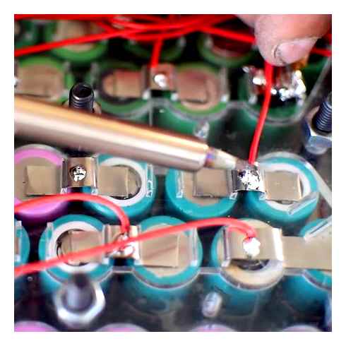
Lay your nickel strip over the tops of your cells and lift up against the welding probes to initiate a weld
Lay your nickel strip on top of the three cells, ensuring that it covers all three terminals. Turn your welder on and adjust the current to a fairly low setting (if it’s your first time using the welder). Perform a test weld by placing the battery cells and copper strip below the probes and lifting up until the welding arms raise high enough to initiate the weld.
You’ll see two dots where the weld was performed. Test the weld by pulling on the nickel strip (if it’s your first time using the welder). If it doesn’t come off with hand pressure, or requires a lot of strength, then it’s a good weld. If you can easily peel it off, turn the current up. If the surface looks burnt or is overly hot to the touch, turn the current down. It helps to have a spare cell or two for dialing in the power of your machine.
This is how your cells should look after the first set of welds
Continue down the row of cells placing a weld on each cell. Then go back and do another set of welds on each cell. I like to do 2-3 welds (4-6 weld points) per cell. Any less and the weld isn’t as secure; any more and you’re just unnecessarily heating the cell. and more welds won’t increase the current carrying ability of the nickel strip very much. The actual weld point isn’t the only place where current flows from the cell to the strip. A flat piece of nickel will be touching the whole surface of the cell cap, not just at the points of the weld. So 6 weld points is plenty to ensure good contact and connection.
Here are the cells with a couple more welds
Once you’ve got 2-3 welds on the top of each cell, turn the 3 cells over and do the same thing to the bottom of the 3 cells with a new piece of nickel. Once you’ve completed the bottom welds you’ll have one complete parallel group, ready to go. This is technically a 1S3P battery already (1 cell in series, 3 cells in parallel). That means I’ve just created a 3.6V 8.7Ah battery. Only nine more of these and I’ll have enough to complete my entire pack.
Now weld the same way on the opposite side of the cells
Next, grab another 3 cells (or however many you are putting in your parallel groups) and perform the same operation to make another parallel group just like the first one. Then keep going. I’m making eight more parallel groups for a total of 10 parallel groups.
Below is a video I made showing how to perform the spot welding steps on a battery.
Assembling parallel groups in series
Now I’ve got 10 individual parallel groups and I’m going to assemble them in series to make a single ebike battery pack.
10 parallel groups all welded up with nowhere to go…
When it comes to layout, there are two ways to assemble cells in straight packs (rectangular packs like I am building). I don’t know if there are industry terms for this, but I call the two methods “offset packing” and “linear packing”.
Offset packing results in a shorter pack because the parallel groups are offset by half a cell, taking up part of the space between the cells of the previous parallel group. However, this results in a somewhat wider pack as the offset parallel groups extend to each side by a quarter of a cell more than they would have in linear packing. Offset packing is handy for times where you need to fit the pack into a shorter area (such as the frame triangle) and don’t care about the width penalty.
Linear packing, on the other hand, will result in a narrower pack that ends up a bit longer than offset packing. Some people say offset packing is more efficient because you can fit more cells in a smaller area by taking advantage of the space between cells. However, offset packing creates wasted space on the ends of parallel group rows where gaps form between the edge of the pack and the ‘shorter’ rows. The larger the battery pack, the less wasted space is taken up compared to the overall pack size, but the difference is negligible for most packs. For my battery, I decided to go with offset packing to make the pack shorter and fit easier into a small triangle bag.
When it comes to welding your parallel groups in series, you’ll have to plan out the welds based on your welder’s physical limits. The stubby arms on my welder can only reach about two rows of cells deep, meaning I will need to add a single parallel group at a time, weld it, then add another one. If you have handheld welding probes then you could theoretically weld up your whole pack at once.
And I’d be theoretically jealous of you.
Since most welders have arms like mine, I’ll show you how I did it. I started by hot gluing two parallel groups together in an offset fashion, making sure the ends were opposite (one positive and one negative at each end, as shown in the picture). Then I snipped a pile of nickel strips long enough to bridge just two cells.
Note that the parallel groups are aligned with opposite poles
I placed the first parallel group positive side up, and the second parallel group negative side up. I laid the nickel strips on top of each of the three sets of cells, bridging the positive caps of the first parallel group with the negative terminal of the second parallel group, as shown in the picture.
I then put one set of welds on each cell end of the first parallel group, effectively tacking the three nickel strips in place. Then I added another set of welds on each of the negative terminals of the second parallel group. This gave me 6 weld sets, or one weld set for each cell. Lastly, I followed up those single weld sets with another couple welds per cell to ensure good contact and connection.
Next, I added the third parallel group after the second, hot gluing it in place in the same orientation as the first, so the top of the pack alternates from positive terminals to negative terminals and back to positive terminals along the first three parallel groups.
Now this step is very important: I’m going to turn the pack upside-down and perform this set of welds between the positive caps on the second parallel group and negative terminals on the third parallel group. Essentially, I’m welding on the opposite side of the pack as I did when I connected the first two parallel groups. Skip down a few pictures to see the completely welded pack to understand how the alternating side system works.
Why do we alternate sides of the pack during the welding process? We do it because in this way we connect the positive terminal of each parallel group to the negative terminal of the next group in line. That’s how series connections work: always positive to negative to positive to negative, alternating between the two.
When we add the fourth parallel group, we’ll again hot glue it in place in the opposite orientation of the third parallel group (and the same orientation of the second parallel group) and then weld it on the opposite side as we welded between the second and third group (and the same side as we welded between the first and second group).
This pattern continues until we’ve got all 10 parallel groups connected. In my case, you can see that the first and last parallel groups aren’t welded on the top side of the pack. That is because they are the “ends” of the pack, or the main positive and negative terminals of the entire 36V pack.
Each of the cell groups not connected at the top are connected underneath
Adding the BMS (Battery Management System)
The battery cells have now been assembled into a larger 36V pack, but I still have to add a BMS to control the charging and discharging of the pack. The BMS monitors all of the parallel groups in the pack to safely cut off power at the end of charging, balance all the cells identically and keep the pack from being over-discharged.
A BMS isn’t necessarily strictly required – it is possible to use the pack as is, without a BMS. But that requires very careful monitoring of the cells of the battery to avoid damaging them or creating a dangerous scenario during charging or discharging. It also requires buying a more complicated and expensive charger that can balance all of the cells individually. It’s much better to go with a BMS unless you have specific reasons to want to monitor your cells by yourself.
The BMS I chose is a 30A maximum constant discharge BMS, which is more than I’ll need. It’s good to be conservative and over-spec your BMS if possible, so you aren’t running it near its limit. My BMS also has a balance feature that keeps all of my cells balanced on every charge. Not all BMS’s do this, though most do. Be wary of extremely cheap BMS’s because that’s when you’re likely to encounter a non-balancing BMS.
To wire the BMS, we first need to determine which of the sense wires (the many thin wires) is the first one (destined for the first parallel group). Look for the wires to be numbered on one side the board. Mine is on the backside of the board and I forgot to take a picture of it before installing it, but trust me that I took note of which end the sense wires start on. You don’t want to make a mistake and connect the sense wires starting in the wrong direction.
Make sure to consult the wiring diagram for your BMS, because some BMS’s have one more sense wire than cells (for example, 11 sense wires for a 10S pack). On these packs, the first wire will go on the negative terminal of the first parallel group, with all the rest of the wires going on the positive terminal of each successive parallel group. My BMS only has 10 sense wires though, so each will go on the positive terminal of the parallel groups.
The wiring diagram supplied with my BMS
Before actually wiring the BMS to the pack, I hot glued it to a piece of foam to insulate the contacts on the bottom of the board and then hot glued that foam to the end of the battery.
Then I took the sense wire labeled B1 and soldered it to the positive terminal of the first parallel group (which also happens to be the same as the negative terminal of the second parallel group, as they are connected together with nickel strip).
When soldering these wires to the nickel strip, try to solder between two cells and not directly on top of a cell. This keeps the heat source further from the actual cell ends and causes less heating of the battery cells.
I then took my second sense wire (or your third sense wire if you have one more sense wires than parallel groups) and soldered it to the positive terminal of the second parallel group. Again, note that I’m soldering this wire to the nickel in between cells to avoid heating any cell directly.
I continued with all 10 sense wires, placing the last one on the positive terminal of the 10th parallel group. If you aren’t sure about which groups are which, or you get confused, use your digital voltmeter to double check the voltages of each group so you know you are connecting each wire to the correct group.
The last step of wiring the BMS is to add the charge and discharge wires. The pack’s positive charge wire and discharge wire will both be soldered directly to the positive terminal of the 10th parallel group. The negative charge wire will be soldered to the C- pad on the BMS and the negative discharge wire will be soldered to the P- pad on the BMS. I also need to add one wire from the negative terminal of the first parallel group to the B- pad on the BMS.
You’ll notice that for my charge wires I used larger diameter wires than the sense wires that came with the BMS. That’s because charging will deliver more current than those sense wires will. Also, you’ll notice the discharge wires (including the B- pad to the negative terminal of the pack) are the thickest wires of all of them, as these will carry the entire power of the whole pack during discharging. I used 16 awg for the charge wires and 12 awg for the discharge wires.
You’ll also notice in the following pictures that my charge and discharge wires are taped off at the ends with electrical tape. This is to keep them from accidentally coming in contact with each other and short circuiting the pack. A friend of mine recently tipped me off to another (and probably better) option to prevent shorts: add your connectors to the wires first, then solder them onto the pack and BMS. Doh!
Below is a video I made showing how to add a BMS to a lithium battery.
Sealing your DIY ebike battery with heat shrink
This step is somewhat optional. You should seal your battery somehow to prevent it from shorting on all of that exposed nickel, but it doesn’t necessarily have to be with heat shrink wrap. Some people use duct tape, plastic wrap, fabric, etc. In my opinion though, shrink wrap is the best method because it not only provides a largely water resistant (though not water-proof) seal, but also provides constant and even pressure on all of your connections and wires, reducing the risk of vibration damage.
Before I seal my batteries in heat shrink, I like to wrap them in a thin layer of foam for added protection. This helps keep the ends of your cells from getting dinged if the battery receives any rough treatment, which can happen accidentally in the form of a dropped battery or ebike accident. The foam also helps to dampen the vibrations that the battery will experience on the bike.
Cutting foam to size before wrapping
I use white 2mm thick craft foam and cut out a shape slightly larger than my pack. I wrap it up and seal it with electrical tape. It doesn’t have to be pretty, it just has to cover the pack. Your next step will hide the foam from view.
Next comes the heat shrink tube. Large diameter heat shrink tube is hard to find, and I got lucky with a big score of different sizes from a Chinese vendor before his supply dried up. Your best bet is to check sites like eBay for short lengths of heat shrink in the size you need.
A quick note: when you get into large sizes of heat shrink, the method of quoting the size often changes from referring to the diameter of the tube to referring to the flat width (or half the circumference when in a circle). This is because at these large sizes, it’s not so much a tube anymore as two flat sheets fused together, sort of like an envelope. Keep that in mind and know what size is being quoted when you buy your large diameter heat shrink tube.
There are formulas out there for calculating the exact size of heat shrink you need but I often find them overly complicated. Here’s how I figure out what size I need: take the height and width of the pack and add them together, and remember that number. The size of heat shrink you need when measured by the flat width (half the circumference) is between that number you found and twice that number (or ideally between slightly more than that number to slightly less than twice that number).
Why does this formula work? Think about it: heat shrink (unless stated otherwise) usually has a 2:1 shrink ratio, so if I need something with less than twice the circumference (or perimeter rather, since my pack isn’t really a circle) of my pack. Since large diameter heat shrink is quoted in half circumference (flat width) sizes, and I want heat shrink with a circumference of a bit more than the perimeter of my pack, then I know I need the half circumference size to be a bit more than half of my pack’s perimeter, which is equal to the height plus the width of my pack.
That might of sounded confusing, so let’s talk in real numbers. My pack is about 70 mm high and about 65 mm wide. That means that half of the perimeter of my pack is 70 65 = 135 mm. So I need some heat shrink tubing that has a flat width (or half circumference) of between 135 to 270 mm, or to be safer, more like between 150-250mm. And if possible, I want to be on the smaller end of that range so the heat shrink will be tighter and hold more firmly. Luckily, I have some 170mm heat shrink tube which will work great.
One more thing to note about large diameter heat shrink: unless otherwise stated, this stuff usually shrinks about 10% in the long direction, so you’ll want to add a bit extra to the length to account for both overlap and longitudinal shrinkage.
But there’s still another issue: now if I just slip my pack inside some shrink wrap tube, I’ll still have exposed ends. This is more or less ok structurally, though it won’t be very water resistant and it will look a bit less professional.
So I’m going to first use a wider (285 mm to be exact) but shorter piece of shrink wrap to go around the long direction of the pack. That will seal the ends first, and then I can go back with my long and skinny piece of heat shrink to do the length of the pack.
If you don’t have an actual heat gun, you can use a strong hair dryer. Not all hair dryers will work, but my wife’s 2000 watt model is great. I own a real heat gun but actually prefer to use her hair dryer because it has finer controls and a wider output. Just don’t go mess up your wife’s hair dryer!
Sliding on and shrinking the second layer
Now I’ve got all of my pack sealed in heat shrink with my wires exiting the seam between the two layers of shrink wrap. I could have stopped here, but I didn’t particularly like the way the shrink fell on the wire exit there, from a purely aesthetic standpoint. So I actually took a third piece of shrink wrap, the same size (285 mm) as that first piece and went around the long axis of the pack one more time to pull the wires down tight to the end of the pack.
That resulted in a total of three layers of shrink wrap which makes for one very protected battery!
Below is a video I made showing how to heat shrink a lithium battery.
Finishing touches
The only thing left to do at this point is to add the connectors, unless you did that before you soldered the wires on, which I actually recommend doing. But of course I didn’t do that, so I added them at this step, being careful not to short them by connecting only one wire at a time.
You can use any connectors you like. I’m a big fan of Anderson PowerPole connectors for the discharge leads. I used this other connector that I had in my parts bin for the discharge wires. I’m not sure what that type of connector is called, but if someone wants to let me know in the Комментарии и мнения владельцев section then that’d be great!
You can also add a label or other information to the outside of your pack for that professional look. If nothing else, it’s a good idea to at least write on the pack what the voltage and capacity is. Especially if you make multiple custom batteries, that will ensure you never forget what the correct charge voltage for the pack is.
You’ll also want to test out the battery with a fairly light load in the beginning. Try to go for an easy ride on the first few charges, or even better, use a discharger if you have one. I built a custom discharger out of halogen light bulbs. It allows me to fully discharge my batteries at different power levels and measure the output. This specific battery gave 8.54 Ah on its first discharge cycle at a discharge rate of 0.5c, or about 4.4 A. That result is actually pretty good, and equates to an individual average cell capacity of about 2.85 Ah, or 98% of the rated capacity.
Manufacturers usually rate their cells’ capacity at very low discharge rates, sometimes just 0.1c, where the cells perform at their maximum. So don’t be surprised if you’re only getting 95% or so of the advertised capacity of your cells during real world discharges. That’s to be expected. Also, your capacity is likely to go up a bit after the first few charge and discharge cycles as the cells get broken in and balance to one another.
I didn’t include a charging a section in this article, as this was just about how to build a lithium battery. But here’s a video I made showing you how to choose the appropriate charger for your lithium battery.
Now it’s your turn!
Now you’ve got all the info you should need to make your own electric bicycle lithium battery pack. You might still need a few tools, but at least you’ve got the knowledge. Remember to take it slow, plan everything out in advance and enjoy the project. And don’t forget your safety gear!
A video version of my how-to:
If you’re like me, then you like hearing and seeing how things are done, not just reading about them. That’s why I also made a video showing all the steps I took here in one single video. The battery I build in this video is not the same exact battery, but it’s similar. It’s a 24V 5.8AH battery for a small, low power ebike. But you can simply add more cells to make a higher voltage or higher capacity pack to fit your own needs. Check out the video below:
I’ll leave you with a little more inspiration
Now I’m sure you’re all jazzed about building your own battery pack. But just in case, I’m going to leave you with an awesome video featuring battery builder Damian Rene of Madrid, Spain building a very large, very professionally constructed 48V 42AH battery pack from 18650 cells. You can read about how he built this battery here. (Also, note in the video his good use of safety equipment!)
About Micah
Micah is a mechanical engineer, tinkerer and husband. He’s spent the better part of a decade working in the electric bicycle industry, and is the author of The Ultimate DIY Ebike Guide. Micah can usually be found riding his electric bicycles around Florida, Tel Aviv, and anywhere else his ebikes wind up.
Комментарии и мнения владельцев
Hello Micah, Thank you for the article! I am currently making a battery for an electronic skateboard, so I need the layout to be as thin as possible to allow ample room underneath the deck. Currently, I have 6 packs of 3 cells welded in parallel, and would eventually like to create a battery which is 9 cells long, 1 wide, and 2 high, for 18 in total (the two packs of nine would then be welded in series). I am wondering if I could be able to make 2 battery packs by welding 3 of my current 3 cell packs together in parallel to make a long, yet skinny pack, and then welding both packs of nine in series using the alternating system. Essentially, I would be creating a pack that would look like 3 of the ones you show above when making your first series connection. Let me know what you think, and thank you!
If you do that (create two 1s9p packs and then weld them in series) you will end up with a 7.4V system. Is that high enough voltage for your needs?
HI Micah, many thank for all the hard work you put into this. After months of trawling through the net, this is by far the easiest and most informative site iv’e seen – Thank you. So after buying a 48v 20 Amp battery from Ebay (and knowing very little at that point), I realized it didn’t have a BMS and heard rumors that if i attached it direct to the controller, it would see it as a short (controller would be closed) and blow the controller. I then bought a “Whale” 48v 17.5 battery with BMS. Question: If put two connectors at the controller end (creating a possible parallel connection) plug in the “Whale” charger at 17.5 Amp and turn it on to pre-load and open the controller, and then on the second parallel connector plug in the 20 amp “Ebay” battery (both “Ebay” and “Whale” are li-ion, 48v but different ampages and cell manufactures: Panasonic and Sanyo). Would the more powerful “Ebay” 20 amp battery blow the “Whale” BMS? I understand that the Ebay battery may run low, but as it is running in parallel to the “Whale”, I’ simply use the “Whale” LED display as rough guid to both batteries charge state (assuming I fully charge both batteries each time before I ride). I simply don’t want to blow the £400 “Whale” battery Thank you
First off: the info you received about a the battery without a BMS blowing your controller is wrong. It’s always a good idea to use a BMS for safety reasons, but as long as the battery is balanced and fully charged, your controller has no idea if it has a BMS or not. All your controller cares about is if the voltage is correct, which as long as the battery is charged, then it presumably will be. Next, regarding your question of paralleling the batteries. Yes, you can parallel them, and you can do it even before connecting to the controller. The biggest safety issue (and damage issue) though is to always be sure they are at the exact same voltage when you connect the two batteries in parallel. The easiest way to do this is only to connect them in parallel when you’re sure they are both fully charged.
Hi Micah, I have built a few 13s lithium batteries in the past year following your instructions. Thanks. I have taken one of the batteries apart to check its condition as it is the middle of winter here in Winnipeg, Canada. Two parallel sets were out of balance with the rest of the pack. I was wondering if there is a way to use my imax b6 balance chargers to rewire the battery and keep each parallel pack in balance for sure! This way I will bypass the bms. Does this make sense?
This makes sense. Yes, it would be possible. You could wire balance connectors and extra discharge plugs to make three packs out of your one 13s pack, such as two 6s packs and a 1s, or two 5s packs and a 3s, etc. Then you’d charge each one, one at at time, using your imax B6 charger. It would take a while, but that’s how you’d do it. Just be careful to not get your connectors confused, as you’ll have three sets of balance wires and three sets of discharge wires.
hello Micah, I finished an ebike yesterday, but i found some major problems on it, The problem is while i riding the bike by throttling, some times the display light dims and low battery voltage caution icon is displaying in the display. and than display shutting off. after that if i try to turn it on again it wont work, so i removed the battery from controller and installed it again than works perfectly, it happens always so i want to remove and install battery again and again, so what is this problem, is this problem is in battery or controller?? Please give me a solution.
Hi Micah, Thanks for the information, it really good for me and I understand much more about battery. I downloaded your video last night. I have different kind of cells which I got from different laptop battery pack. My question is, can I use these cells together because the current ratings on each are different. Thanks again.
It’s best to try and match the cells as closely as possible based on capacity by using a lithium cell tester like this one. If you plan on using the battery you build for a high drain application, different current ratings will be more of an issue. If you have many cells in parallel and will only pull low current from each one, then different current ratings are less of an issue. It’s always best to use perfectly matched cells, though I know that’s not the cheapest option and is outside of the budget for many.
Great article. You say that “The BMS I chose is a 30A maximum constant discharge BMS, which is more than I’ll need. ” How do you determine this exactly? Your battery is a 36v 8.7Ah and I guess it has something to do with the maximum continuous discharge rate. It would help me (and maybe others) to explain why 30A is more than enough for this battery. I read that ebike batteries should have a high max discharge rate (some state 10A, others 5C per cell). Is that only desirable for high-speed acceleration or needed in general? I have the option to purchase Samorsung 18650 22f (2250mah) batteries at a very low rate of €1 per cell, but they have a max discharge of 2C(4.5A). Would they still make a good battery pack?
I was using that battery on an ebike with a 15A controller, so that BMS was capable of twice the power I need, meaning I would only be stressing it to 50% of it’s potential by pulling 15A. That’s why I said it’s more than I’ll need. But if I wanted to put it on a bike with a 45A controller, then it would NOT be enough, and I’d need a more powerful BMS. Different cells are rated for different current ratings, you’ll have to check with the discharge specifications provided by the manufacturer for each cell. 22f cells are quite low capacity and not very strong. They will work for an ebike (and are about the cheapest good quality cells out there) but they aren’t optimal. You’ll end up with a larger and heavier pack as compared to more energy dense cells like Panasonic 18650pf or Sanyo 18650ga cells.
I purchased the 220v welder, which obviously was intended to run on non-US half of a phase 220v, Of course we have full single phase 220v, so could you supply me with a hint on how to wire the unit for US 220 v. thanks
I wasn’t aware that the 220V welder wasn’t compatible with US 220V, I’ll have to look into this and see how to remedy it.
Micah, I wouldn’t say incompatible but us 220 uses the full phase peak to peak of both legs of the elec drop. European and others uses a half phase (I believe) where zero to peak is 220v. Have you had a chance to look into this for me as my welder and box of new 18650’s are sitting idle waiting for me to start welding. Thanks
I’ve checked with a few people that have bought 220V european welders and used them in the US, and they all say they work fine (besides one that broke a few months later from an unrelated issue). As far as I can tell, regardless of whether its half or full phase, the transformer inside still sees the approximately 220V it’s looking for. Have you tested yours on 220V yet?
I haven’t yet as I am unsure how to wire the welder to plug into the us 220 since it is across the full phase rather than the half phase of european 220. I would appreciate anyone’s wisdom on this.
I haven’t done this myself, but I did some searching and found this on Endless Sphere: https://endless-sphere.com/forums/viewtopic.php?f=14t=80018p=1180159hilit=ebikeschool#p1180963 He is in the same situation and wired his 220 welder to use the 220 in his garage in the US. Looks like that’s your answer, and he’s got the wiring setup he used there too.
hello, i want to add a ignition switch to my battery pack(10s4p,Samsung 18650-26j cells) for on and off the battery, i bought an ignition from ebay(http://www.ebay.com/itm/321748146034?_trksid=p2055119.m1438.l2649ssPageName=STRK%3AMEBIDX%3AIT),i planed to install this key switch in series to my positive wire from battery pack, but discharge current is up to 20 Amps, so i couldn’t install that switch in series, could you please suggest me an idea on how to install this ignition switch, do i install a relay or what can i do?
Absolutely, a relay is the way to go. Use the keyswitch you bought to activate the relay, then the relay will carry the heavy current flowing through your battery’s positive discharge wire. Alternatively, you could install 9 or 10 of these switches in parallel. Just make sure you mark your keys accordingly

The article was extremely informative, thank you. I’ve found everything but am struggling with good cells. At Aliexpress there are many choices but I’m struggling to get near the 2/cell mark you mentioned as a limit for decent cells and still find performance criteria of a good battery (or at all). So far I’ve found NCR18650B but it appears to have a 2C discharge rating for a 3400mA cell. At 4P this is more than enough but seems low for LiIon so I wonder if it is good? The price is 163 shipped to USA for 10s 4p 40 pieces to make 36v 13.6Ah. After adding shrink wrap, BMS and nickle strips I’m at 213 before buying a spot welder (200). I can buy on the same site a 36v 15Ah Li-ion pack for 248. https://www.aliexpress.com/item/US-EU-No-Tax-DIY-lithium-18650-battery-pack-15AH-36V-Electric-Bike-battery-for-36V/32757165516.html?spm=2114.13010208.99999999.274.JmcpBS As much as I want to build a pack just for fun and like buying tools like a spot welder I’m afraid of getting crappy cells at a high price. Whatj’s a good cell to charge at 1C for quick turn around and stay at a low price per cell? 36V 12A would be ok, more is a bonus. Thanks! Carl
First of all, NCR18650B cells cannot be discharged at 2C. Those are 5A MAX cells, and really you should keep them closer to 1C to keep them cool and happy. They are economical cells. They do better when in large parallel groups so you can take advantage of their high capacity without the downside of their low discharge rate. They are great cells, but not for low AH packs. I should really change that 2 cutoff to more like 2.50, which is more reasonable for quality cells. Basically, the cheapest ‘good’ cells are Samsung 26F cells, which can be had for usually around 2.50 – 2.90 if you are buying in any large quantity, like at least 100. Expect to pay more like 3.00 or so if you’re buying only 40 cells. 26F cells are also limited to 5A discharge though, so you’ve got the same issue as with the NCR18650B cells from Panasonic. 1C charging is too high for most Li-ion. It’s too much to ask for right now, to be able to charge an entire pack in one hour. It can be done, but it’s not healthy for the cells. Aim for 0.5C at the most. I usually don’t go past 0.3C on charging.
Hi Micah your post have been extremely infomative, i am trying to DIY a pack for my electric scooter for a 36V and around 5AH pack should it be 10S 2P? sorry if i am not clear, kinda a beginner myself. and BMS wise what kind should i use?
If you are using 2.5AH cells then yes, it will be 5AH with a 2p configuration. If you use cells with higher capacity, like Sanyo GA cells that are 3.5AH, then you’ll have a 7AH pack with only 2p. Make sure your cells can handle the current that your electric scooter (and namely the controller) will try to draw from it.
I have two of these batteries: http://www.electricbicycleworld.com/li-3/ They are 36V 11.6ah using Panasonic (Cell Model NCR18650PD). Typical cell capacity is 2880mAh and minimum cell capacity is 2730mAh. I want to take the apart and use the cells to make a 48V 16.8ah battery. Would you advice against this? Would 48V provide a noticeable difference in the power of my motor? (It is a 500W Falco Direct Drive Hub Motor)
That’s a good option. You’ll notice about a 30% increase in power, as well as a 30% increase in speed. Your motor can certainly handle it, the question is if your controller can. Make sure it’s rated for 48V or you’ll need to swap in a different controller.
Hi Micah. Thank you very much for the material, excellent. Congratulations! I want to build a 4S5P pack and use BMS. I would like you to point out to me an appropriate charger for this battery pack. I thank you. Sandro
Hi Micah, Great Article. I am also now trying to build an e-rickshaw by my own. The spec is mentioned below. Rickshaw weight (including battery) = 400kg weight planning to be loaded on the rickshaw: 350kg wheel dia= 12-14 inch, tyre width= 4-5 inch So do a 48V controller is enough for my application. Approx how much wattage/power is required for the above spec. Awaiting for your valuable feed back.
Cool project! I’d check out electric rider (www.electricrider.com) as I know they have some good electric rickshaw and electric tricycle kits. You’re looking for a strong 48V motor that is geared really low. You want torque, not speed. With slow speed, something in the 1,000 – 1,500W is probably enough. Just don’t expect to be flying down the road…
Hi Micah, Great website! I’m reading through it all as I build my E-Bike. My question for you is, if I just want to run a BMS for balance charge purposes only and want to wire the battery discharge directly to the motor how would I do that? Would that be a good solution as long as I monitor battery pack voltage during rides? Thanks!
As long as you monitor your pack voltage so you don’t go too low during rides, then yes that would work. You’d simply run your discharge negative wire straight from the.1 terminal of your battery out to your controller, instead of from your.1 terminal to your BMS’s B- pad. But that removes the ability for the BMS to cut off the current when the voltage goes too low, so you’ve got to watch for that.
Hello Micah, Thank you for the very informative post, and it has helped a lot. I plan on building a battery pack with 20 cells with blocks of 4 in parallel, and then I am going to put those in series to make an 18.5V, 13.6A pack. Sorry if these sounds a little bit foolish, but I am not sure what kind of BMS I should be using. Would I be able to use any BMS or would there be an issue with having extra wires if the BMS can power more batteries in series?
It’s a good question. You need to use a 5s BMS. You can’t use a BMS rated for more cells because if the BMS see’s that cells are “missing” it will likely trip the protection circuit and your battery won’t provide any current. I’m not sure how easy a 5s BMS will be to find. A quick Aliexpress search shows me that something like this will probably work.
Micah, First off thanks for the great info! I’ve been thinking of a flat build for a DIY electric skateboard and your video has been one of the most informative ones yet! Sorry if this has been asked already but there are a ton of Комментарии и мнения владельцев to wade through. Ten individual 18650 cells in series at a nominal voltage of 3.6 Volts would give me 36 volts. Assuming they are 2500 mAh a piece, then if I put 4 of these 10 cell in series packs together in parallel I would have a 10 Amp Hour battery correct? The same applies if I were to wire a pack together with 10 “4p” cells together in series. I’m trying to determine what the benefit of 10s4p over I guess what would be “4s10p”. Lastly, there seems to be some agreement that there should be a copper wire reinforcement down the serial connection side. Is this necessary in your experience?
As you described, 10 cells in series and 4 in parallel would be a 36V 10AH battery (for the 2500mAh cells you mentioned). A 4s10p battery would be different (about 15V 25AH). I’m not familiar with this copper serial connection you’re talking about. I guess you mean to reinforce the series connections to handle more current? As long as you are using enough strips of nickel (and ensuring that it’s pure nickel and not nickel coated steel) then you shouldn’t need copper reinforcements. I try to use at least 1 strip of nickel for every 5A my battery will carry. So if I’m looking for a 20A max load, I’d use 4 strips of nickel in each series connection. That’s easy to do if each cell in a parallel group of 4 cells is connected to the next group by one strip each.
Hi Micah, great post. I have three questions and I apologize if any have been answered earlier…there are a lot of Комментарии и мнения владельцев: 1) When you connect the set of ten 3P groups in serial you use three nickel strips for each positive-negative connection. Wouldn’t one strip be sufficient? 2) Could you have connected 10 cells in serial and then three sets of 10S groups in Parallel? 3) If you could create a kind of jig box that uses pressure to hold contacts to cells instead of welding, would there be performance issues?
1) no 2) yes 3) yes Just kidding, here’s a little more detail. 1) Yes, actually you could just use one strip of nickel on series connections to make the electrical connection, but one strip of 0.15mm thick nickel strip can only safely carry less than 10A. Ideally you want at least one strip for every 5-7A you plan to pull through the battery. 2) You can definitely do the series connections first, it is just habit for me to do parallel connections first. Also, on larger packs I like to do parallel groups first and then glue them together and do the series connections as I glue each group. 3) People have explored this idea a bit on Endless Sphere, and while it can be done, it has a lot of room for error, mostly in keeping the spring loaded contacts permanently against the cell terminals and in keeping the contacts from corroding. Spot welding is the best method, in my opinion.
Hey, Love your YouTube videos! I’m actually looking to make an electric longboard on the cheap. I have an 18V motor (from a battery drill) that I want to power and I have purchased 10 (AA) 3.6V 3000mAH Lithium-ion batteries with the intention of connecting them together in a series arrangement to run the motor. What would be the best way to arrange them? And is there a need for a BMS for a smaller arrangement? Or would it be more time effective/safer to just charge each battery individually? Any help is appreciated. – Kind regards
I’m a little worried that your batteries aren’t what you think they are. If they really are AA sized, which is rare in the lithium battery world, then they are not 3,000 mAh. Next, 10 cells in series is going to give you 36V, which is twice what your 18V drill is rated for. 5 cells in series and 2 in parallel would be a better method. I usually recommend a BMS but you can skip it if you have another way of diligently monitoring your cell voltages and then charging using an RC style balance charger like an iMaxB6 charger through an JST-XH connector.
hello, I bought a charger from ebay, i measured its output voltage, it says 42.5V,i made a battery pack with Samsung ICR18650-26F cells, 36v pack (10s4p), will this charger damage my battery pack?
I have a homemade battery made up of 84 NCR18650b cells that I bought (in other words, I didn’t make the battery myself). Anyway, I lost the charger for it at Burning Man, and now I’m going nuts trying to figure out what kind of charger to buy. The arrangement of the batteries is odd. Part of the battery looks pretty straight forward in what I believe is a 8s6p design, but the rest look different… they are set up like a 4×3 rectangle framed by 2 L’s. I would have happily uploaded a picture, but that doesn’t seem possible. Is there anyway I can send you a picture to show you what I mean? I would sooooooo appreciate your help! Toda raba! Liz
Hello, what is the model yellow transparent adhesive for assembly in the video on YouTube. it’s special? thank you for the tutorial
It’s called kapton tape. It’s non-static, non-conductive and heat resistant. It’s really great stuff. Electrical tape works too, but kapton tape is nicer to use.
hi micah, i am building a 10s4p 36v 18650 battery pack for my ebike, what gauge silicon wire you recommend for discharge and charge wires, i am using 2.5 amp 42.5v li-ion battery charger bought from ebay(http://www.ebay.com/itm/281639749374?_trksid=p2057872.m2749.l2649ssPageName=STRK%3AMEBIDX%3AIT), and 10s 36v 30amp bms bought from ebay(http://www.ebay.com/itm/182247900118?_trksid=p2057872.m2749.l2649ssPageName=STRK%3AMEBIDX%3AIT) and 500w 36v controller.
For discharge wires you’ll want something bigger, like 14 awg silicone wire. 12 awg would be better but might be overkill for your use. For charge wires, 16 awg silicone wire would be fine and you could probably get away with 18 awg silicone wire.
Hi Micah, I am from India. At first i would like to thank you for this amazing page.(Its full of knowledge). I would like to know what input in terms of voltage and current i should provide to my battery of 36V 8.7AH. And also how the calculation goes if i want to build a battery for some other Voltage and current specification ? I am not intending to use BMS. I am planning to build my own BMS. And Can you also suggest if any BMS Building guide is available online that you can suggest ? Thanks in advance.
Charge voltage for li-ion cells is 4.2V per cell maximum. So for a 36V 10s battery you’d want to charge it to a maximum of 42V. Charging slightly lower will increase the life of the battery, but isn’t a requirement. Charge current depends on the cells. Most cells can take at least 500mA, some considerably more. It’s hard to know what cells you’re using. Assuming they are 18650pf Panasonic cells like I used here, 1A per cell would be fine, giving you a charge rate of 3A. They can actually take more than that, but there’s no reason to push them too hard if you don’t have to.
Excellent tutorial. I am just collecting the materials to build my ebike and battery. One question regarding the specific battery BMS you used in this build: It uses a different wire for charging vs discharging the battery. Does this mean that the regenerative braking feature cannot be used for this battery? I say this because I am assuming that the wire from the motor that connects to the battery and receives power from the battery would be the same wire that provides power in reverse to the battery when regenerative breaking. With this particular BMS, would it require a different wire to do the regenerative braking? Thank you Brian
Hey Brian, good question. You can actually do regenerative braking this way, the only problem is that you won’t be using the balancing circuit part of the BMS as it will charge straight back through the discharge circuit. Theoretically this is fine, with the exception of one specific case where this could be a problem. If you charged your battery at the top of a huge hill and then immediately rolled down that hill for a long time while using regenerative braking, you could actually overcharge the battery. That scenario is pretty rare though.
Hello Micah, Thanks so much for this excellent information. I was wondering how to calculate the total amps for the entire battery? I’m trying to determine watts from this as I have a 24V 500 watt Rayos electric bike and am working to build a 24V 20 Ah battery (7s7p) battery and would like to know what watts it is capable of providing. Thanks again, Chris
Hi Chris, The watts (power) the battery can provide is totally dependent on the type of cells and the BMS rating. So until I know more about your cells, I can’t help you. But for an example, imagine you used cells that were rated at 5A each. 7p x 5A = 35A total power capacity. 35A 24V = 840 watts, the total amount of power your battery can handle. But now let’s assume you used a 20A BMS, meaning the BMS can only handle 20A continuously. That’s your limiting factor, so your new total battery maximum power is 20A 24V = 480 watts. Now just substitute the actual current rating of your cells and BMS to solve for your battery’s power capacity.
Miach, Another excellent answer, thanks so much! Now it has arisen a few related questions, if you don’t mind answering them. I’m using authentic Samsung ICR18650-26FM cells. I had already purchased a 24V 15A BMS before I slightly understood all of this. I was also able to obtain more cells since my original idea, so I was planning a 7S10P pack (around 30Ah), 70 cells total. I see each cell can do around 5A, making a 10P pack put out 50A total. If I stick with my 24V 15A BMS, that will give me 15A 24V watts, or 360 watts total for my 500 watt motor. I’m going to number these to make it easier: 1. Does this mean I could get more range out of the battery pack per charge as I’m only using 15A of the 50A it can produce? Or is the extra amperage the battery can put out wasted? 2. Would a 24V BMS that could do a higher amperage (maybe even 50A) provide faster speeds of the E bike but deplete the battery faster than my current 15A BMS? 3. Lastly, I assume if the BMS battery were able to produce the 50A X 24V watts of 1200W that my electric motor would only ever use the 500W it is rated for? As in the E bikes controller would only draw around 500W? Thanks so much again for the help. I’m a first time battery builder and am becoming obsessed with all the calculations, ensuring I don’t fry anything, like my electric motor or BMS.
The extra amperage that the battery could output isn’t wasted, it’s just sort of a safety factor. It means you aren’t stressing the battery to its limit. Also, batteries only get their full rated capacity at lower discharged. So you’re more likely to get the full capacity now than if you actually pulled 50A out of it. 2. No, it wouldn’t really increase speed at all. It would increase the amount of power you could create, but that would only help on up hills and during acceleration, not on top speed on flat ground. 3. There’s something that I think you might be missing here. The factor that actually limits current draw is the controller, not the motor or the BMS. Those are “rated” for 500w and 15A, respectively, meaning they won’t overheat at those values. But both can physically pass those values if you force them to. It’s the controller that is actually “pulling” the current. So you should check your controller to see what its current limit is. If it is a 15A limit controller, then it won’t physically pull more than 15A. The fact that your battery can technically put out 1200W just means that it has “oomph” than you’re using, and you’re giving it an easy, healthy life. But if you switched to a 50A controller, suddenly you’d be pulling the maximum current that your battery can supply (and probably overheating your motor if you pull that 50A for a long time).
Excellent information! I will check out my controller rating. Hopefully I can still use my existing BMS that I waited to come in from China for. Thanks so much, again.
Micah, Is it possible that the controller for this Rayos 600W (sorry thought it was 500W but it’s actually 600W) is inside the electric motor itself? I traced all wiring on the E bike but find no controller anywhere. Do you see anything majorly wrong with using a BMS to charge the cells but not discharge, as in sending the current from the battery directly to the controller / motor? I’ve been unable to find a BMS that can do 30A that isn’t very expensive. A side note, I was able to test amperage while riding and around 20A gets me 9 miles per hour, that is where my multimeter tops out! I’m 235 pounds. I’m guessing I need around 30A to get the 16 MPH I get now with the existing LiFePO4 battery pack. Thanks again, Chris
Just got your ebook.great detailed writing and resources. Definitely worth every penny. I need to build a 56-60v battery that I will be using to convert a bike with 20″ moped rims and a 48v 1500w 46.5 kmh — 28.8mph 13 5T winding rotor hub motor. I’m looking more for range than speed (mostly flat where I live), although I would like to top 30mph. If my math is right, in order to accomplish this I need to build a pattern that is 16s6-8p. Which 18650 cells should I choose? I’m also not sure which BMS I should use? And then which controller is best for this battery and motor setup? I’ll post the links to the parts I’m currently sourcing and let me know if you think there is a better set up or parts. Thank you
Update: after reading thoroughly through your ebook I think my understanding of ebike builds has grown tenfold. Thank you. I have come to the conclusion that a 48v battery would probabky be sufficent for my needs. I need to ride continuously for at least 7-8 hours–but prefer up to 10 hours– at 15-20mph everyday. Although I also need a top speed of 30mph, at times. If my math is right, in order to accomplish this I need to build at least a 14s8p battery. After running these specs through a simulator I found that the power starts to drop at about 1150 watts and 20mph. Better voltage and capacity recommendation for my needs? Which S and P Config? Which 18650 cell will perform best? Should I just use any standard 14s 30aH BMS? Most sufficent wattage and max capacity of controller for battery and hub setup? What else should I be considering in this build? Any help would be much appreciated! Thx
7-8 hours of continuous riding is going to require a huge battery, we’re talking in the 50AH range, depending how much you’re pedaling. Do you really need this much battery/run time? If you’re building a huge capacity battery, high energy density cells with low discharge rates like the Panasonic 18650B cells are probably the way to go in order to have the best bang for your buck. I’d look for a 48V 1,000W controller.
I need help. I want to upgrade my existing 48v 20ah lithium battery to a 72v 20ah battery. Here’s what I got. A chinese made pack 48v 20ah made of lithium ion 18650 cells rated at 3.7v 2.3ah configured in 9p 13s with a bms of 30a continuous discharge. This is what I want to do. Buy another chinese pack 24v 20ah configured 9p 6s with (hopefully) same cells and join them together. Will that give me a 9p 19s pack ? Then install a new bms for 72v 19s and 60a continuous discharge. Will this work ? If yes can you recommend a bms and a controller for above. Please let me know. Thank you
Yes, that’d work, but I’d get an additional 7s battery so you have 20s total. Also, you should know that the older your original 48V battery is, the more time it will take your new 72V combined battery to balance, as the first 13 cells will likely have less capacity in comparison to the newer cells. I made a video recently showing how to do this upgrade that you’re talking about: https://www.YouTube.com/watch?v=9KHo-T74IWA
Hi Micah, Great and really useful article ! I just have a simple question: I would like to replace the Nicad battery 24V / 5Ah of my old Yamaha PAS XPC26 with a 7s3p and maybe try a 8s3p for something more “punchy” (hoping the controller will not burn …). Do you think I can buy a 10s BMS and use it with a 7s or 8s battery? In this case, what should I do with the spare balance wires ? Thank’s for the help! Benoit (Paris)
Sorry Benoit, but that won’t work. The BMS will expect the full 10 cells and when it sees that cells are missing, it will assume they are at 0V and not provide any power. You need a 7s BMS, which are pretty commong. 8s will be harder to find for li-ion, but you could do 8s with LiFePO4 and those 8s BMS’s are common.
ANBET says August 13, 2016 at 7:08 pm Your comment is awaiting moderation. Hi Micah I use Google Translate to write the next REPLLY. I wanted to thank you for sharing with us the knowledge THAT you I have accumulated regarding electric bike. After reading your lovely article, I decided TO try to build my electric bicycle battery. I opened the original battery ׁׁׁ (type “FRUG”), to study the arrangement of the cells. The battery is 10 S4P 36A 11.6A But the 4 P ARE arranged in a square shape ,each side OF THTE SQUARE consisted of 2 CELLS, so I built LIKE SO. ON THE ENGINE IS WRITTEN- VOLTEG: 36V OUTOUT: 250V The controller says: RATED VOLTAGE-36V, MAXIMUM CURENT 12A. To save customs duties, and with knowledge that appears on YouTube I built – SPOT WELDER WITH PROBES. It took me over a year to finish the project THAT With your help, I decided to make. BUILDING The SPOT WELDER and THE battery gave me great pleasure AND relaxation and became a real hobby for me and I am very grateful to you for that. (I am 65 years old who lives in Tel Aviv, and believe me moments of relaxation are a rare commodity in my country). When I finished it ,I charged THE BATTERY AND got about 42 volts- I was happy about. BUT WHEN I tried to connect the battery TO THE CHARGING plug of the bike …. unfortunately there is no response and I have no idea why. Maybe you have a great idea where I failed? I’d love to get your help. Angie Israel Tondobski Reply
Shalom Angie! It’s hard to say for sure without seeing your work. I imagine that either you have a bad connection somewhere, or else you have some cells that are weakened and drop their voltage too low when a load is applied. I didn’t quite understand from your message: did you rebuild the battery using the cells in your Frog battery, or did you start with new ones? Old or damaged cells could cause the problem you are experiencing. To help solve the problem or at least narrow down the possibilities, I’d start with the following steps: 1) Try plugging in a battery that you know works on other ebikes. If it works on your ebike, you know the problem is definitely in your battery. 2) Try measuring the voltage of the battery while you plug it in and attempt to power the bike. If you see the voltage drop instantly when you turn on the bike, you’ll know you’ve likely got an issue with weak cells or a poor connection that causes a voltage sag issue. 3) If you can, try swapping out the BMS to determine if a bad board is giving you an issue. And as always, double check every connection to ensure you don’t have any loose or poorly made solder or weld joints. B’hatzlacha! –Micah
Hello Micah, I was just wondering if its possible to just replace the 18650 cells from my previous battery and keep the wiring and the circuit board or BMS aswell instead of buying everything new? Kind regards Chris
Yes, it’s technically possible, but sometimes it is easier said than done. If the cells are on the edge of your battery, it’s much easier to cut them out (by the nickel, not by cutting the actual cell!) and replace them. If they are sandwiched in the middle of your pack then you’ll have to do a lot more pack surgery to get in and replace them. But yes, it’s possible to just remove them and replace them with new, good cells of the same capacity. At the same time though, think about if that is what you want. It could be that those cells died because of a malfunctioning BMS unit or old wiring. Putting new cells in their spots could just wind up killing those new cells in a few days or weeks. I’ve seen that happen as well. So make sure you check everything and consider all of your options!
Hello Micah, Sorry Micah, I did’ntvknow how to send mail to you, so I used this reply to reach you. I have a short question; is it possible to use a 13s BMS for a 11s battery pack and how should I connect the sense wires in that case. The reason is that I was unable to find an 11s BMS. Thank you in advance.
No, if you use a 13s BMS with only 11 cell groups, the BMS will sense that two cell groups are missing and that the battery voltage is not correct, and it will not allow the battery to work.
Hey Micah There’s a lot of topics entries on this site, so I hope I didn’t overlook someone else asking the same quetions. I’ve been reading a bit about how Batterybro.com makes sure to test there batteries are genuine, and how it seems they still get a lot of fake batteries from China. When you buy on Aliexpress.com how to you know and make sure the batteries you buy are genuine? there’s a lot of sellers how did you find yours? I hope you can help in the jungle of fake batteries Ps. thanks for a very inspiring site!! Regards Kristoffer
The best method is to use a trusted vendor. They interact with the cell providers and are the best way to confirm whether cells are fake or not. It can be incredibly difficult to tell whether a cell is fake or not just by picking it up from the table. There are some giveaways like different printing on the wrapper, slightly different color, different stamp, different weight or different shell design, but all of those can be mimicked. That’s why I use only a handful of vendors that I’ve worked with continuously and who I know have always given me good quality cells. I had to go through some low quality ones until I found the sources I buy from now. If you want to test cells from different vendors, the best thing to do is run them through a discharger, preferably a fancy graphing one, and preferably at a high current rating close to the maximum discharge rating. Fake cells are lower quality and won’t be able to provide the same capacity, and will have a larger voltage sag under higher loads.
Hi Micah, Having built a 13s4p battery to the best of my ability and hooked it up to my 48V 1000W ebike conversion kit…. the lights on the throttle turned on and the wheel spun! Initially I thought the project was a success but after mounting the battery and controller onto the bike and taking the bike for a test spin I ran into a major problem. The bike was more than happy to run and pull me along as long as the throttle was kept very low (~30%) but as soon the throttle was turned more or I came across a slight gradient uphill the system would cut off (no lights or power). I then have to plug the battery into my charger to ‘reset’ it before I can then plug it back into my bike and make it work again. I have to keep the throttle low whilst I am riding on the bike before it cuts out but if the wheel is spinning freely in the air then I can max out the throttle and make the motor run at full speed. This had led me to believe that if there is too much load being exerted on the bike (i.e. the current being drawn from the battery is too high) then either the BMS or the controller trips and cuts out. However I am reluctant to believe that the BMS is causing the trouble as it has a 40A rating on it (this link shows the exact BMS) http://www.aliexpress.com/item/Electric-motor-car-13S-48V-40A-BMS-lithium-ion-battery-BMS-Used-for-48V-20Ah-30Ah/32484213150.html?spm=2114.13010608.0.62.evx6sX. Do you think it is the BMS or the controller that is cutting out beyond a certain load or something else completely? As far as I am aware the battery is fully charged and balanced (I even left it charging for 2 days once as I read that it can sometimes take this long to balance the cells!). Any ideas or help would be HUGELY appreciated as I have come so far just to fall at this hurdle!!
Do you by any chance have some spare parts you can swap in? A spare controller would you let you know if the controller is faulty and tripping early. Another battery would show you if the problem was battery related. than likely this problem is BMS related. The BMS usually trips in that scenario for one of two reasons: 1) The load pulled by the controller is too high for that BMS, or 2) one or more cells are weak or damaged and when the load is applied strongly, it causes the voltage of that parallel group to drop below the LVC of the BMS. What I would recommend doing is trying to ride again and when the battery cuts off, take it inside and measure the voltage of each parallel group before you try recharging it. Measure straight on the battery. If you find one group that is lower than the rest, it is likely the problem. It might have risen back up to a reasonable voltage with no load, but it can still be lower than the rest. If you don’t find that, there’s still a chance that it’s the problem, and that the cells simply rose up to a higher voltage and matched the others again once the load disappeared. But it also may be that the load is too high for the BMS. Do you have a cycle analyst? You could slowly increase the throttle and watch how much current you are drawing until the point of cutoff. If it’s well below 40A then you’ll know it’s not a high current cutoff. Lastly, there’s a small chance that it’s just a faulty BMS. This method is annoying, but if all else fails then you can try swapping out the BMS. than likely though, the BMS is doing it’s job because one of the cutoff conditions is fulfilled and it’s just trying to protect the pack. Oh, one last thing. If you have a poorly formed connector or the wires are fraying, that can increase resistance and cause a voltage drop that might trip a cutoff condition. Just another thing to check for. Good luck!
hi Micah, a littel of topic… anyway im from isreal and i wanted to know if there is any isrealy sites are forms that you can recommend on ebike topics form and israeli perspective?
To be honest I do most of my ebike work in English, but I do know there are some good groups for Israeli ebike riders, so I’d recommend starting your search in that area. B’hatzlacha!
Hi, I want to build a 36v ebike battery for my 36v 500w motor. What battery you recommend for me which gives the enough current and capacity. My plane is to build a battery with 40 cells 10 in s and 4 in p,
I’d recommend going with a cell that can output 10A, giving you 40A continuous power rating. You’ll use less than that, meaning the cells will be happier (and cooler). Something like the Sanyo 18650GA or LG MJ1 would give you good power and capacity (both are around 3,400 mAH per cell).
How would I go about making a 48 V battery in the same manner that you did? I would just add three more 3-packs (alternating direction as always) onto the end of the finished battery, right?
Hi! thanks a lot for your blog. I have one simple question. I buy that pink cells, Samsung ICR18650-26F. The cells have 3,9V, is a little too, only one with 3,82 and the other 3,87. I want to do a pack with 4parallel and 7serie (28 cells), it is acceptable conect them? Any sugestion is welcome. Thanks!
Hi Micah! I really need your help to understand what is happening here. At this moment I have a motor (nominal voltage 24V; 250W) running with 4S4P, the bateries came with 3.9V and I need to dissipate some energy because next month will be without using. The BMS is for 7S, I connect B1, B2, B3, to the negative of the first serie. B4 is connected to the positive of the first serie, B5 positive of 2nd serie, B6 positive of 3rd serie, B7 positive of 4rd serie. With the Multimeter I see that is everything OK, I see the voltage of the 4S in B and P-, but when I connect the motor nothing happens, the voltage goes to zero. At this moment I want to discharge the batteries and I connect B- to B and is working OK, of course. What you think is happening? The BMS is damage? bad connections of sense wires? Please help! Thank you a lot
You’re trying to use a 7s BMS with a 4s battery, which will not work. The BMS thinks the voltage is too low because it is expecting 3 more cells.
If those are new cells then I’m surprised that the voltages aren’t identical. That difference (0.08V) is about the farthest difference I’d want to see between cells. Ideally you should charge that 3.82V cell up a bit more before you connect it in parallel with the others. I’d run tests on all of those cells though with a capacity tester to ensure they are good quality cells though. Genuine cells straight from the factory should all have identical voltages.
Bigger is better! And I know a better way batteries should be made. I use 560 of the Panasonic 18650b battery cells with 3.4AH per cell, wich in the end gave me (7kwh battery ebike!), that’s more than 300 miles battery range easy. And I’ve learned that these batteries can be assembled like Lego blocks instead and eliminate harmful heat from soldiering, and wastful glueing. The benefit is a battery pack that can have removable, repairable, and reconfigurable battery cells! Its called (battery blocs) patiented by Shawn McCarthy. Unfortunatly its not the cheap method and requires a 3d printer to make. It spaces the cells slightly apart for better air cooling. Mine are packed into 4 PVC tubes run either at 103.6v or 51.8v. I believe along with some experts that a BMS is not required and can cause battery cells to fail early!, and a proper set voltage monitor and regulator prevents over discharge damage and you need to a timer and monitor the cell voltages with cell monitors while charging. Cooling setup would be a pluse to extend life. That’s all for now, best luck to all battery builders.
BMS’s aren’t required, they just make life easier. As you mentioned, if you don’t use a BMS then you’ve got to diligently monitor your cells and use balance charging to manually balance your cells. A BMS just takes care of this hassle for you. A low quality BMS can cause problems, but good quality BMS’s shouldn’t risk cell damage.
Hi Micah, I am looking at Lifepo4 batteries now but what I ask is independent of which cells one goes with. What I need is a battery system that I can use at 48V or 12V and the switch between these modes (as well as charging) is smooth and safe. Say, a trolling motor and an ebike. I was thinking on building or getting 4 of 12V20Ah packs, which you can push into the actual system either paralel or serial. I can get e.g. this: http://www.ev-power.eu/LiFeYPO4-batteries-12V-1-1/Lithium-Battery-LiFePO4-12V-20Ah.html However, the description says The monolithic 12V batteries do not have any PCM (any electronics) inside. They consist of finely balanced cells with identical perfomace. The battery must be managed as a single monolithic 12V block. Now, how do I charge and balance this system? I can not reach the individual cells inside the batteries. All the BMS I found goes for 3.2V cells or sets of cells. This question is really independent of the actual product and goes as well for a Li-Ion setup: If I want to build an Nx12V variable system, how do I do the BMS and charging smartly? Thanks, Straw
12V increments are easier to do with LiFePO4 due to the 3.2V per cell. So for 12V, 24V, 36V and 48V they go 4 cells, 8 cells, 12 cells and 16 cells. Li-ion is more annoying because the 3.7V per cell doesn’t play as nicely. The general convention for the same 12V increments is 3 cells, 7 cells, 10 cells, and 13 or 14 cells. 3 cells is just a bit low for a 12V system (about 11V nominal) but will work for most applications until the voltage drops to about 9.5 or 10V depending on your device’s cutoffs. Regarding the balancing issue, if you’re using those packs that claim to remain in balance then I’d imagine you can just trust them. If their packs had problems with balance then they’d probably be having tons of returns. Worst come to worst you can occasionally open the case and measure the cells to make sure they are all staying balanced. One word of advice: be very careful with the series/parallel switch setup. If you make a mistake or the switch melts you could end up shorting your batteries and ruin the whole lot…
Excellent write-up! I have one question you’d likely be able to answer and it relates to continuous discharge current. Is this rating cumulative? For example, a INR18650HG2 cell has 3000mAh capacity and a max continuous discharge current (CDC) of 20A. If assembled into a 4S4P, that’d be (4S, 4 3.7v) 14.8V. Would it be 20A CDC or 80A CDC (as in 4P = 4 20A)?
I want to use my two 4Ah Ryobi lithium batteries 18volts in series for 36 volts. I have a charger for them. they use 15 batteries each so 30 total, they are 50 each. This seems similar to your 36v build for about 3 each so 90 total, plus a spot welder for 1oo. I want to get a 38v/750 48v/1000w rear motor recommended from your web site from aliexpress. Do you think that these will work for my bicycle?
People have successfully used drill batteries on ebike setups. The problem is 4AH is not a lot and you’ll find that your batteries run dry quickly.
Hi, How much sense wire to BMS i need to buy and replace a old 48v 52 cells battery? its 6 group with 8 cells each and one last group has only 4 cells.
I don’t know, you’ll need to open your battery and check it yourself. You should double check your cells too, it should be 13 groups of 4 cells.
Hi Micah, Great video, I’m planning for a 8S5P and I’m wondering if I can use the 10S BMS that is use had in the video. If I don’t use pins 9 and 10. I’m having a hard time finding an 8S BMS/PCB. Thank for your time.
I’m sorry but that’s not going to work. The BMS will cut power as soon as it realizes that cells 9 and 10 are missing.
Hi, Thank for the great article. I made battery packs already, do you have any recommendations on chargers. I have a 53 volt pack 30 amp hr. I don’t know what charger to buy, and I’m worried as lithium batteries tend to blow up if not handled correctly. Thanks
I assume you mean 52V (14s, or 14 cells in series) which is a somewhat common lithium ion battery configuration. It works with most 48V setups but provides a little more power than a standard 48V (13s or 13 cell) battery. A good charger I recommend for 52V 14s batteries is this one.
Hi Micah! I do have a 60v 20amp electric scooter that runs on lead acid battery. I want to replace them with lithium ions. May I know if my calculations is correct, 16s7p? Thanks!
16s or 17s would both be good options. The p number depends on the type of cells you use, but 7p sounds reasonable for many cells.
I love this article and I am inspired by the knowledge here, I have a question, I need to build a 72v battery and the one I’m looking at is using 38160 cells, these cells are very expensive so how can I manage this the best using the smaller normal size cells like you’re using! Do I really have to make a battery 20 cells deep to reach this and to bump up the amp hours I would let say go 10 wide for a 30 amp hour right? Pretty close! Big battery but is it feasible or is there a better product
The cells you are talking about are the Headway LiFePO4 cells, right? These are quite different cells. 18650’s are li-ion, and have a higher voltage than those big cells. For a 72V pack, yes you’ll need 20 cells of 18650 li-ions in series. If they are 3AH cells, then yes you’ll need 10 in parallel for 30AH. But that’s a huge pack. 200 cells total for about 2.2 kWhrs!
Hi Micah,I am from INDIA want to construct a 36v,15 ah,peak current 15 amp,continuous current 6 to 8 amps. Now ipurchased 20 pcs new IFR 18650 lifepo4 rechargeable cells,and a BMS36v,lifepo4 BMS12s forE.Bike lithium battery pack 12s,36,v,PCm.How many cells total i have to use for my aim?What kind of charger (specification) i have to purchase? Your article and reply to questions are interesting.please guide me. With best regards. Thanking you. Sundaram Ramakrishnan
Hi Sundaram, I’m not aware of many 18650 LiFePO4 cells, are you sure you are using that chemistry instead of standard lithium ion? Perhaps can you provide a little more detail about the specific cells you’re using?
Hi, I´m really happy to have found this website. I´ve found a motor online in China from nnebikes. It says: Wattage: 400w Voltage: 60V/72V/84V/96V motor design: 5000w brushless GEARLESS motor efficiency: 85% My question is: What battery set up will work for this motor? obviously 60 to 96V but I´m unsure with the ah´s. I need to know what minimum ah will work, I´m on a tight budget especially when shipping from China to Colombia is so expensive. Any advice will is greatly appreciated. Danl
Hi Danl, that sounds like a very high power motor. Most consumer ebikes are in the 36V-48V range, so if your motor is advertised as being rated for those higher voltages then it’s definitely a more serious motor. If you’re looking for a ready-built and relatively inexpensive battery, then something like this might work for you, though I haven’t personally used that battery. You can of course build your own battery just like I did in this article, and that way you’ll be sure to get exactly what you’re looking for. The AH’s required will depend on the quality of the battery. A batter rated for higher current will require fewer AH’s than a lower quality battery. I’d aim for at least 20AH, if not more on a motor of that size. It’s going to eat your battery quickly, so you’ll want more capacity to be able to ride longer.
Hi Micah, I’m building my first battery pack. I am looking for some nickel strip and bought one but according to your test, it looks like the one I bought on ebay is nickel plated (bummer). I checked your links but your links also say nickel plated. Are you sure your links are selling pure nickel? The link here says “1M 8mm x 0.15 Nickel-plated Nickel Strip Tape For Li 18650 Battery Spot Welding” The link on your YouTube video says “Free shipping 18650 battery nickel strip 0.12mmx8mm nickel plate 18650 26650 cell nickel belt Lithium battery connecting sheet” I just want to make sure that I get pure nickel this time.
I’m sorry to hear that. I recently went through and changed the nickel strip links as I found some vendors had switched to nickel plating.
Hi I’m in the process of putting a Bafang BBSHD 1000w 48V motor on my bike. But I’m unsure on what battery I’m going to need. The bike is to get me too and from work and it’s about a 25 miles round trip with some big hill’s. I would like the battery to have a bit more rang just in case. what size battery would you recommend.
It’s always hard to say exactly how much AH’s someone will need because every case is different. With that powerful motor sucking lots of juice and big hills though, you are going to want a minimum of 48V20AH. If I were you I would try to go even higher, but it may be even better to simply have two batteries at that point. It’s annoying to swap them, but if you ever had a problem with a 48V30AH battery that destroyed the pack, it would be a big investment straight to the garbage. A problem in one of your smaller packs would mean you still had the other. It’s not likely to happen, but it’s something to think about.
Hi Micah. Well, I’ve finally built a pack, which in the end turned out to be a 16s6p/7p made from recycled dead laptop batteries, charging to 67.2V and has a secondary offtake for a controller on the 13s positive (i.e. to route 16s to the FETs and 13s to the control circuit). Some of the groups were OK for 12Ah from 6 cells, others needed 7 cells; I just used what I had and as I got the laptop batteries for free, it was better for me spend the time testing them than to use 80 new cells, which would have been quite expensive. I’ve used two 10s BMS boards (the same ones as in your pictures) and overlapped the sensing wires on four of the groups. I also soldered rather than spot welded and used 1.5mm2 solid core copper between cells, pre-bent to zig-zag shapes on a jig (current is then distributed between them). Offtakes were 4mm2. Soldering technique to minimise heat on the cells was to paint the cells and the wire with flux, load the soldering iron tip with enough solder to make the joint and then, while holding the wire on with the back of a wooden pencil, touch the molten solder to the cell/wire interface and immediately remove the soldering iron tip. This worked really well in terms of soldering quality and the solder cooled very quickly indeed. I cleaned the flux off with a baby wipe and then dried it with some paper kitchen towel. It was an interesting project to say the least, particularly how to link the Ch- and the P- from the BMS taking its B- from the 7s negative termination to the positive of the 6s group, given that there are two routes (i.e. charging and discharging), so connecting both simultaneously would override the function of the BMS. In the end, I opted for a DPDTOFF rocker switch, as using diodes introduced forward voltage drop and this interfered with charging enough for me to have second thoughts. This arrangement does require that the BMS be “flashed” to initiate it, which can be done by the charger in charging mode but for discharging, I found that shorting the B- and the P- for less than a second initiated the BMS and it then latched itself on, so I installed a reset button. If I had used a DPDT switch without an off position then I would not have needed to do this. However, when the BMS hits a low voltage group e.g. going up a steep hill, it will not automatically reset when the voltage recovers, so you need to use the reset button if you want to get the last bit out of the battery. I’m toying with latching this button when discharging, as the voltage drop knocks the controller out, so I think I’ll get a reaction like traction control, without having to manually reset the battery (which is annoying as it’s in a backpack). The result is that my 700c wheeled bike with a 250W 300 rpm motor from a 20″ wheeled bike does 34mph, which I’m more than pleased about. Anyway, I thought I’d share all that for the sake of advancement of knowledge, as I’ve picked up quite a lot from this site and like to give something back
I’m sorry but I’m not certain. Here in Israel we are on 50hz so I haven’t tried that model on 60hz. I do however have some friends in the US that have that model on 60hz. They have been happy with it, but I haven’t used it myself so I can’t say how it compares to my experience.
Hi Micah, I have been looking up materials and researching where to buy them for my battery pack. I’ve come to the exact conclusions (and almost the exact same materials) that you write about in this great article. Too bad i didn’t find it earlier… Doh! I have now come to the conclusion however that i want a pack that is 48V and capable of running a 1000w motor for atleast an hour. I live in a hilly area, i use a downhill bike (heavy) and im not the smallest guy. Im feeling a bit insecure about putting too many cells in parallel. Through the years i’ve read that the consesus is that more than 4 cells in parallel is a risk. Since a 13S4P pack is about 12Ah (with good batteries) i was wondering if you had any input on how i should move on? The idea of putting two 13S4P packs in parallel with their own BMS (maby with a 2S BMS or a fused balancing connection between them) has come to mind. Thoughts? Thanks for the great articles!
I don’t think there is any danger to parallel more than 4 cells. Tesla cars have literally hundreds of 18650 cells just like these paralleled. The issue is that if you ever did have a problem with one cell, like a factory defect that caused it to short circuit, it could die and drag all the other cells down with it, killing the entire parallel group. That’s why Tesla uses individual cell fusing, but that’s not really employed on the small scale like for ebikes. My daily driver ebike has 8 cells paralled (14s8p) and it’s been working great for a long time. You can certainly make two 13s4p packs and parallel them after the fact, but don’t be afraid of making a single pack. As long as you use good quality cells, the risk of a parallel group dying is incredibly small.
hello, i noticed that bms installation is different (as i guess) from the video (https://www.YouTube.com/watch?v=rSv9bke52eYindex=10list=LLDXj2cy8mbQoc0dz3RO3zFw) i have watched before. In this video bms wires were connected on the negative poles of batteries lifepo4. In my amateur opinion i could not understand how we organize BMS connections for my 13s pack. if you illuminate me, i will be preciated. thanks again.
Hi! I’m planing to build one of my own batteries, and here is the main question Will I still need BMS if I’m using protected cells? I know i’ll get less capacity but better performance, because each cell is being monitored separately. I would like to hear your opinion on this. Thank you! Great post!! By the way, you can build your own spot welder from old microwave transformer. will try it soon on some dead cells.
Actually, it is not recommended to use protected cells in ebike builds. There a few reasons but the main ones are 1) unreliability of the protection circuit, 2) many points of failure, and 3) lower discharge current of individual cell protection circuits. It would be much better to go with a BMS to protect the cells. It will also balance the cells, which individual cell protection circuits will not do.
Hi Micah I’m just stating out on a project and if you were to select a BMS which manufacture would you recommend?
The single best manufacturer is BesTechPower, but their BMS’s are really expensive and they have a minimum order quantity of 2. For ‘best bang for your buck’ BMS’s I’d recommend Greentime BMS’s. They are great for most ebike applications outside of serious hotrods and speed machines. I use them on most of my packs.
Hi, many thanks for this excellent and comprehensive post…have done a bit of spot welding / battery construction and this article is extremely instructive in considering further plans Can I ask you for a couple of thoughts also… Firstly, can you provide a link / source for the 10s BMS you are using here (can see various discussion / links but not the actual same one)? Secondly, what is your take on modular plastic battery spacers (e.g. http://www.ebay.co.uk/itm/50x-EV-Pack-Plastic-Heat-Holder-Bracket-Battery-Spacer-18650-Radiating-Shell-New/351681365193?_trksid=p2047675.c100005.m1851_trkparms=aid%3D222007%26algo%3DSIC.MBE%26ao%3D1%26asc%3D36381%26meid%3Dfc487881e617412ba361731154a742b5%26pid%3D100005%26rk%3D5%26rkt%3D6%26sd%3D262123820960). Clearly this adds a significant volume penalty and a smaller weight / cost one, but if this is not an issue then how would you rate vs glueing? I can see the benefit of having a space between the cells to limit heat / electrical conductivity in the event of some kind of melt down, but any thoughts? Finally, have you used the type of spot welder shown with hand held probes? Can see the benefit of greater reach, but do you know if this gives as neat a result (my spot welder there is a very firm press up to activate, hence the discharge only occurs when the tips of the welder are pressing the strip firmly against the top of the cell so i assume ensuring a tight weld) thanks again!
The spacers you linked to make battery building a bit easier as you can set it up modularly, but as you indicated, they add a good amount of volume to the battery. I like to make my batteries as small as possible so I rarely use them. When I do, I use these ones, but it’s not very often. You would think they would help with cooling, but in reality there is little to no difference. They do create an air gap between cells but because that air is trapped inside the pack and can’t get out, it just turns into an oven. So you can glue your cells together and have them cook on a skillet or use those plastic spacers and have them bake in an oven I’m mostly kidding, but if you use cells that are rated for more current than you’re trying to pull from them, you’ll create a lot less waste heat and both options will be perfectly fine and healthy for the battery. The BMS I used is this one. Lastly, regarding the spot welder. I actually prefer to use the kind like you said, with the two arms that lift up and provide equal pressure at each weld. The kind with two long welding cables like this welder has both options which is nice, especially for if you need to reach to the middle of a pack to make a repair or if you missed a weld. I mostly use the short rigid arms though and just weld one row at a time before adding more cells – that way I can reach all the cells with the short arms.
Micah, What a great article! It has opened my eyes to lots of possibilities. Being new to this I had a couple of questions. I am interested in building a spare battery to give me more range on the Faraday Porteur. My question is how to connect the battery I would build to the bike. The main battery resides in the downtube and the connection is hidden. They offer an ancillary battery that plugs into the charging port which is what I would like to build myself rather than buy. Do you think this would be possible? Where could I find a connector that would match? Any concerns? If so, what other options do you suggest? Thanks so much for the help!! Ancillary battery: https://www.faradaybikes.com/product/auxiliary-battery-pack/ Charger connection: https://www.faradaybikes.com/product/extra-charger/
Wow, that’s a really interesting way to do it. So their auxiliary battery connects to the charge port of the primary battery, which means it’s not actually powering the bike but rather just charging the primary battery, which then powers the bike. Not the most efficient way to do it, but it’s simple and elegant. To answer your question, you can definitely build your own auxiliary battery. It looks like they used a fancy right angled female XLR connector, but I imagine a standard female XLR connector will fit just as well. I’m not sure if you’ll be voiding your warranty though by connecting your own battery. Those XLR connectors can be purchased all over ebay and probably even at your local electronics shop. From what I can tell, the Faraday Porteur uses a 36V 5.8AH battery made from the same cells I used on the battery in this article. They only have two cells in parallel though, not three like in my battery shown here. You can build a battery just like theirs, or a 36V battery of any capacity. You could make a 12AH battery and triple your total range! Heck, you could even take a premade battery like this one and just replace the discharge cable with a XLR connector – it’d be an auxillary battery over three times as large as theirs for 2/3 the price!
Micah, Thanks so much for the info, that sounds great and an exciting option! I understand the warranty issue but aside from that, you don’t see any issue than with building a battery of any capacity and just making the discharge cable with an xlr connection to plug into the bike. Would I need a different cable to charge the battery or does it charge via the xlr connection like theirs? Here is one more link with a few more answered questions about their auxiliary battery if you wanted more info. Thanks again, this is really exciting, I just want to make sure I don’t fry anything https://www.faradaybikes.com/tech-updates/ Jonathan
Hi Jonathon. You’d need a female XLR cable for the discharge port on your new battery (so it can plug into your Porteur’s charge port) and you’d need a second XLR connector, this time a male, for the charge port of your new battery. That way you could use your original Porteur’s charger to charge both batteries. Interesting that they claim the controller is balancing the two batteries. I highly suspect that is false, and just marketing fluff, but who knows. They probably have a simple diode built into the internal battery. I checked with a friend and he reminded me that it would be a good idea to include a diode in the discharge cable of your auxiliary battery. That way if you ever plugged in your auxiliary battery when it was low on charge and the bike was fully charged, the bike wouldn’t try to charge your auxiliary battery in reverse.
Micah, Thanks again for the great info, that is really helpful. I just have one last question. On the XLR connections there is a hot, neutral and ground. It appears on the battery you linked to that there are just two wires, how can I ensure which prongs of the male XLR connection on the Porteur are hot and negative? Also, do I just leave the ground spot on the female XLR connection open since there is just a hot and negative wire? Since you mentioned the charger, the link you sent me came with a 2 amp charger but it would take 10 hours to charge that size battery. Could I use a larger amp charger like 5 or even more for faster charging? How do you tell what is too much so you don’t damage the battery? Thanks!! Jonathan
You want to be really sure you get this part right, and if you aren’t certain, I’d recommend having an electrician or the company help you. But you can determine positive and negative on the charge port by using a digital multimeter on the DC voltage setting. Probe between the three pins on your bike’s charging port to find which pins give you a positive readout of between 30-42V (Depending on level of charge). When you find it, the positive pin will be on the red probe and the negative pin on the black probe. Be careful not to short the pins together or touch the probes together, those XLR connectors are cramped quarters. And again, make sure you’re certain you’ve got it right – connecting something backwards could damage your bike’s battery.
Also, the best method for adding an auxiliary battery would be to connect it when both batteries are full, or at least at similar discharge states. That means the auxiliary battery won’t have to work as hard transferring energy to the internal battery, as they’ll be depleted together at similar rates. And the diode in the auxiliary battery will ensure energy only flows one way (towards the internal battery).
I figured this would be a critical step I wouldn’t want to mess up. Thanks for the advice on using the multimeter. That’s good to know as I thought I might need to open up the controller and see which wires went where on that male xlr connection which I guess would be an option too. Thanks again!
hello, firstly i would like to say that i think this is a brilliant article its really helped me understand a lot more about how this works and how i can use a similar system for my project but i am a little confused and i was hoping to pick your brains…. i have the exact same BMS but i only have 6 cells, 2p x s3. i have 2x 3.7v @ 2000 mah batteries in parallel connected to another 2 parallel batteries in series and another parallel pack in series if that makes sense to make a total of 11.1 v @ 12mah for a small project. the problem i have and the bit im confused on is this, i understand the negative on the entire pack goes to the negative on the BMS and the positive of each parallel cells goes to each sense wire but where are the charge and discharge wires going ? am i corrrect in saying that the positive of the pack goes to the charge and discharge socket on the BMS and that when the pack receives its charge it charges the pack and the discharge is when the pack is under load from the output of the pack i.e what ever its connected to for example your bikes motor? in your tutorial you havent shown how you connected the parallel groups of batteries together in series to give you the final pack voltage and capacitance but i’m assuming you linked them in series to get the toal 36v but on the pictures the first and last cells are split compared to the doubled up cells you have through out. am i also correct in saying that if you have 2 batteries connected together to form a cell then you dont need a sense wire on each battery because the two batteries are considered to be the same battery and when they charge and discharge they equalize as one shunts the other ? sorry for so many questions i have googled and googled and googled and as Einstein once said the definition of madness is doing the same thing over and over and expecting a different result, many thanks in advance.
My series connections are between each group of 3 parallel cells. So all the connections that go across the short side of the pack are parallel connections, and all the connections that run along the long end of the pack are series. It doesn’t always happen that way, but the shape of this pack forced that geometry. For charging, it will depend on the BMS, but generally your positive charge lead goes straight to the pack’s positive end, and the negative charge lead goes to the BMS’s C- pad. The sense wires generally connect to the positive of each cell group, but sometimes there is one more sense wire than parallel groups because the first sense wire is intended to connect to the negative of the first cell group, then all the subsequent sense wires connect to the positive of each cell group. Each BMS should be labeled on the board to show where each sense wire goes (B1-, B1, B2, B3, etc…) The P- pad on the BMS is intended to go out to the discharge connector, and the B- pad is intended to connect to the negative of the first cell cell group (B1-). I hope that info helps.
Great article! Have ordered everything BUT i have a big problem with the spotwelder. Most homes in europe are limited to 10A and this spotwelder alone drags 15A just to powerupp. I can even start it without blowing both fuses! And when welding it wants 50A-800A which you need a an actual POWERPLANT for! Has anyone had a similar problem and know how to get around it?
Yes, I’ve seen this problem. Homes that have only a 10A circuit breaker are often not enough for these welders. The room I wanted to use mine in had a 10A, so I switched it for a 20A breaker at the breaker box and now it works fine. As an aside, the 50A-800A you’re talking about is during the output, and that’s at a very low voltage, which is the reason for the high current draw. But that power equals a much lower current on the input end where it draws from the wall outlet.
Thanks for the quick comment. I took it too an electronics lab i stockholm and had 3 expert look at it, we tested it for an hour in several outlets marked 16A but we could not get it to work. So its NOT MAX 15A as stated on the device but closer too 20A. The EU plug is only rated to max 16A so this would need a different contact to be able to work safely in europe. Also changing the fuse to a higher one could cause the wires to start a fire and the whole house would burn down if the wires are not thick enough. Also in sweden a fuse gets bigger as they are rated higher so you can fit a 20A fuse in a 10A slot, for safety. I hope someone can recommend another spotwelder or some other kind of Technic to fuse batteries with wire (except soldering). This has been an expensive ordeal and if not even a techlab with endless lasers cutters and cool cants get this machine even to power up, its something wrong with the machine. Thanks anyway, excellent article.
hello sir. nice guide FOR battery pack li-ion… i will try an electric bike kit for my 26″ MTB. and buy 1000w hub motor kit. i can solve my battery problem (expensive you know) with Li-ion pack. i have some questions, 1. do i need Smart charger though installing BMS? 2. do i try to build 18650 battery pack or lifepo4 (38120) battery pack with BMS (its little expesive choice)? 3. i saw 18650 and 26650 Li-ion batteries which are more powerful such as 6000 – 8000 mah. i think they are fake. i need 48v 10ah or 20ah minimum i guess as a pack. your advices are important. thanks for all…
You’ll need a CC-CV (constant current, constant voltage) charger, but you don’t need a Smart charger like for charging RC lipo batteries used in hobby remote-controlled planes and helicopters. 2. I highly recommend using a BMS in both Li-ion and LiFePO4 batteries. As a Li-ion vs LiFePO4 question, one isn’t necessarily better than the other. Li-ion will be cheaper and probably more powerful, but LiFePO4 is going to last years longer, so it’s all about what you want in your battery. 3. Yes, 18650’s with capacity ratings of 6000 or 8000 mAh are fake. The technology simply doesn’t exist to put that much energy in a cell that size on an economical level. In a few years we might be there, but not right now. Currently, the biggest cells are in the high 3,000 mAh range for 18650’s. 26650’s are larger cells and so those can have higher capacities, but there are many fewer options and variety of 26650 cells, so 18650’s are the common cells used in ebike packs.
THANKS for your quick reply. everything that i need i had but spot welder. then i m building a new MASTODON branded spotwelder i will feed back the results and spot welder if i can with your permissions.
Hey there. I bought the pure nickel strips linked in your article, but they fail the spark-test. I’m sticking them in salt water to see if they’re really steel. I also don’t have a spot welder, and for the purpose of building a single 16S2P pack, I’m not sure I want to splurge on that extra 100. I do have a whole tub of flux and a temperature-controlled soldering iron, so I’ll be attempting to solder the cells instead (extra hot and fast with lots of flux to avoid conducting too much heat into the battery internals from dwell time). I was wondering, though, if I could use thick gauge wire instead of nickel strips (copper wires are much more accessible). Would there be any downsides to that, given that I’m going to be using solder anyway?
Interesting, thanks for the update! Which length of nickel strip did you get? (I linked to a few different options for amounts). I’d definitely like to hear back from you about the salt water test. Regarding the soldering of cells: generally it is not recommended as no matter how you do it, a soldering iron will still transfer more heat than a spot welder. That being said, I have seen packs that have been welded using both solid or braided copper wire. I’ve also seen someone use copper wick soldered to the cells terminals. It’s impossible to know exactly how much of an effect that the heat transfer had on the cells but if you don’t mind taking a risk of some level of deterioration of the cells performance, then it technically is possible to solder the cells together. Here is an example of someone that used copper plate soldered to the cells: https://endless-sphere.com/forums/viewtopic.php?f=14t=76237
I bought this specific nickel strip. I guess I’ll just have to risk some deterioration on the cells. I don’t think there’s much of an effect, as I did it on an old 18650 cell to test. The joint and surrounding areas were cool to the touch within 1-2s of removing the heat. I did some googling after my comment, and apparently copper strips turn green very quickly under the high currents an EV draws. I think insulated copper wires might resist corrosion better. As for my “nickel” strips, it appears to have failed the salt test as well. http://imgur.com/CA7rY7L
Update: it looks like my nickel strips might be pure nickel after all. The salt water appears to have a suspension of brown precipitate which looks and smells like rust. However, after fishing the nickel strip out and rinsing it with water, it still appears to be silver in colour and not rusted: http://imgur.com/a/8DI4t
Hey, I’m about to build my 16S2P pack from 32 Samsung INR18650-25R cells bought from batterybro.com. How far apart can their voltages be when you connect the parallel packs? They seem to all be charged between 3.52V and 3.56V.
When I buy new Samsung cells, they are all within one hundredth of a volt. Pretty much always all 3.60V, or occasionally I’ll have one at 3.59V. Four hundredths of a volt is probably fine to parallel them, but I would be more worried about why the cells aren’t all the same. If they are brand new cells from the factory, they should be nearly spot on. These might be more expensive than what you paid, but I get my Samsung 25R cells from this vendor, where I know they’re genuine and straight from the factory, and all come at exactly the same voltage.
Micah- Thanks so much for all this great informating, Im going to purchase the ebook for sure! One small question first, though. I’m building a 13s8p 18650 pack from laptop batteries for my bfang 750w 25A pedicab. I already have 45V 15 Ah LiPo setups from china, but want to up my Ah. Would this BMS be satisfactory for the job? Thanks so much! Dustin Dean
Hi Dustin, I’m not sure which BMS you’re referring to, but a BMS that I have used on at least a dozen 13s packs is this one.
Hello Micah, I build battery for ebike from cells of laptop batteries and have a question: To check if the cells can be parallel I choose in the charger (imax b6) storge option and got four batteries with 3.81v. Is it possible to use them that way or I should full charge them and then check the voltage ? Thank you, Ofek
The batteries can be paralleled at any charge level as long as they are all the SAME charge level, i.e. same voltage. If they are all 3.81 V then you can parallel them, or you can charge them all to 4.2V and then parallel them, both are fine options. But if you are putting many parallel groups in series then it is a good idea to get them all to the same charge level first. That will make the first charge of the whole pack much easier as the BMS doesn’t have to balance cell groups that are at very different charge levels.
Really nice article you made here. very helpful. I do have some questions about the BMS board you used. Would you know where I could find any type of schematic for it because im trying to see whether I can use more then one of those BMS boards on one pack
Thanks for the kind words! Unfortunately I don’t have access to a schematic. I got that BMS from a Chinese reseller and I would be surprised if even he has a schematic. I have seen people parallel BMS boards on a single pack to get higher current output but I haven’t tried that myself.
This is truly inspiring, this has helped me out in so many ways, I have a few questions I want to ask please. I was looking to withdraw amps by making connections from the battery directly but charging it through the bms as my bms is similar to yours max withdraw of 40 but I need upto 50a. and also are most BMS self balancing ? Meaning wil they always try to balance themselves even when they are not being charged ? Hope to hear from you soon kind regards
Technically yes, you can bypass the BMS for discharging and just charge through the BMS but this is not recommended. It is better to just choose a BMS that can handle your 50A discharge. BesTechPower makes some great BMS units that can handle 50A and more, depending on the model. They have many options. Most BMS’s do not balance during discharge, only during charging. Some cheap BMS units don’t even have balancing functions, so make sure you read the details if you are getting a very cheap BMS.
Hi, Dear Micah, I was looking on the web for a BMS, fortunately I found this page and I’m extremely glad for it because this your article, is very well done and very well explained. So, Dear Micah, I have an old 12V DC Brush Motor which its consumption is around the 12A, 13 A and I built a Battery pack, with two groups of batteries, (4S6P)(4S6P), which makes a total pack with 14,8V 30A. To make this battery pack I used 18650 Samsung Cells 2600 mAh. I need your help, please. If you don’t mind of course. Because I don’t really know which is the right BMS that I should buy. I need a BMS which could makes all the control and protection of the battery pack. Could you advise me which BMS that I must buy, and where if you know, please? Thank you Sorry my english it isn’t the best. Best Regards Carlos Pote
Hi Carlos, For your 4S battery, assuming you’re running those two packs in parallel, you’ll need a 4S BMS. Here is a 4S BMS capable of 30A discharge, which will give you a nice safety factor.
Just to thanks you for this guide, a must-have for any battery builder, I always use this guide to redirect newcomers looking for a broad view of this, Thanks MicAh
Hi Micah, Thanks for the guide, I’m looking to build a battery pack and this is the most precise while concise information I’ve seen so far. I’m planning on building a 10S12P pack for usage on a custom DPV (Diver Propulsion Vehicle). For packaging purposes, it would be best for me to split the battery pack in several battery modules instead of a single block of cells. If I regroup my 12 paralled cells in 10 modules, can I then join these in series using single wires (one for neg, one for pos) between modules, instead of wiring each terminals of each cells like you are doing. Could this affect BMS and/or have any negative impact on cells balance? I’m not sure if you are doing so for redundancy purposes or if it’s actually better chemically/electrically talking. Thanks for a fellow mechanical engineer in Canada
That is definitely possible, but keep in mind that the 10 modules you want to connect in series will only need one wire between them. You don’t need to connect the negative and positive of each to the next – you only need a wire from the positive of module 1 to the negative of module 2, then a wire from the positive of module 2 to the negative of module 3 and so on. Two things to keep in mind: 1) make sure you use a thick enough wire between the series-wired modules, especially if you are going a long distance. The longer the wire, the more resistance there will be so compensate with a thick wire. 14 or 12 awg silicone wire would be great. And 2) you need to also make sure you’ve got thick enough wire for the balance wires from the BMS (since you’ll of course need to run all the small BMS wires to the modules as well). Ensure those solder joints are strong, as they’ll be on long and flexing wires with increased chance for damage or breaking at the joints. Those are normally tiny wires but if they are going to be extra long then something like 20 awg should be fine.
I’ve been dealing with 18650 cells for many years having my own product which users them (ShiftEzy Rohloff Electronic Shift). – 4 in series. Never had a comeback! I’ve standardised on the Panasonic protected NCR18650B. As a result, I have many in stock. I’m building a two wheel e- recumbent and wish to build my own battery. I am using an 8Fun Befang 1000W mid drive unit. Do you think I could make use of 56 protected cells I already have (14S4p) without a BMS?
Actually, the protected cells aren’t a great option for ebike packs. The protection circuit on every cell can overcomplicate things, not to mention that it usually isn’t rated to handle the same current the cell could without a protection circuit. It is must more recommended to remove the protection circuit when building ebike batteries and use a single BMS on the bare cells instead.
Hello Micah: Thanks for this most interesting and useful article! I want to build a battery in a 39mm x 520mm seatpost for fueling a 250W motor that normally uses a 7.2 Ah – 25 V bottle-shaped battery. The new seatpost battery should only have an autonomy of 7 miles of steep hills (40%) between each daily charge. What are your recommendations? Happy day! Fred
40% grade hills? That’s huge! You’ll definitely want a cell that can perform at high current since you’ll be pulling peak power from those cells to get up those big hills. Something like the Samsung 25R would be a good choice for this application.
Hello Based on your article I wanted to build my own battery for my bike, to replace my existing battery, but I run into problems almost from the beginning. First thing is regarding the cells – I have just order some Panasonic 18650PF like yours by chance (I was looking for Samsung). The delivered cells were made and charged in 2014, and the measured voltage now is around 3V (/- 0.1v). So the voltage is basically the same for all of them but there are old, I think, even thaw never used and stored in a warehouse. Can I use them? Should I charge them individually or is ok to make the hole pack and charge it as a hole battery (13S4P) at the end? Or return them back? Thanks for this detailed article.
To be honest, if they were marketed as new and when they showed up you found they were two years old, I’d try and get my money back if possible. If not possible, try charging them individually. Some of them might come back but others might be dead. The tricky thing is that they will likely not be able to deliver their full capacity anymore and the actual capacity will likely vary from cell to cell. Two year old cells at a very low voltage are quite a gamble.
Great article and if you’re producing multiple batteries, etc then clearly this is the way to go. However… I’m thinking about extending the range of my 250W ebike (a Greenedge CS2) by wiring a battery in parallel as a one-off project. My thinking is that as it would halve the load on each of the batteries, it would reduce output current and voltage drop under load. This I’m thinking would allow use of a simpler constructions, since the stress on each cell would be reduced. Proposed construction: – 10 cells in series mouted in a 21.5mm OD plastic tube (standard item from the hardware store). There is minimal lateral movement of the cells within these tubes – Busbar end connections (15mm copper pipe or similar), one of which would have compression springs to put some compression on the cells. – The whole thing would be wrapped. – 4 tubes, giving a 10s 4p arrangement, which is the same as the standard battery – Connect the battery in parallel with the existing at the output terminals, which means that I would be charging and discharging the batteries as a pair. My thinking is that because each of the batteries is only 50% stressed, that the probability of problems due to overcurrent, etc. would be negated and I wouldn’t use a BMS for the supplementary battery. I understand that this is a cheapskate/bodge arrangement, so I know it’s not something you would recommend. However, my question is that would this be inherently unsafe and what would the risks be? Thanks
Well, you’re right that I wouldn’t recommend it! I admire your ingenuity but there are a couple big issues with this setup: 1) You have 4 groups of 10 series cells but no way to balance between them. The 4 cells need to be paralled before they are wired in series otherwise they will get increasingly out of balance with each charge/discharge cycle. 2) I’m not sure you’d get a good enough contact from a copper spring or busbar that is just held on the end of the cells in compression. The copper will also corrode over time and caused increase resistance at the point it touches the cells and problems down the road. You’re absolutely right that doubling the capacity of the battery by running two packs in parallel will essential halve the load on each pack, but I still don’t think it would get it down to the level that you could rely on compression fit spring contacts to safely carry that current, let alone the balance issue of not having the 4 groups individually paralleled at the cell level.
Hi Micah After writing my question, I did more research on these cells regarding overcharging and over-discharging and I see where you’re coming from regarding not having connections between the parallel cell blocks to smooth out differences between individual cells. So as a permanent installation, it’s not going to work. However, I’ve had another thought, which I’ve put at the final paragraph. Ideally, I would buy a battery with the same type of connection and just carry the spare one unconnected and swap them over but I don’t seem to be able to find the type of battery case for sale anywhere. It’s a quick release bottle type battery that has two sprung terminals about half inch in diameter that contact with two large terminals on what I think must be the motor controller integrated into the bottom of the bottle mounting bracket. Maybe another way forward is to buy a pannier mounted supplementary battery pack (a proper one with a BMS) and to install it in parallel with the main one. The question then becomes whether to connect between the sprung terminals that go to the motor controller (which I believe to be the best thing to do) or into the little charging port jack. I presume that the charging port is connected to the charging side of the BMS and I don’t know how much current that port would take or whether it’s even a good plan to charge and discharge the main battery at the same time. I see significant potential for a high current through that small jack once I discharge via the main battery and a voltage difference exists between the supplementary batter and the main battery. Thought regarding temporary supplementary battery: If the 4P10S multi-tube arrangement was for occasional use on long journeys, then it would be reasonable to release all of the cells and to charge them individually or in parallel to about 4V using a normal little single cell charger. Each would then be “top balanced” yes? Then mount them in the tubes, compress and connect the top terminal array and good to go. I’ve still got the quandary about whether to connect them in parallel to the main battery large output terminal. Cheers Lee
Hi Lee, I would advise against connecting one battery to the other’s charging port. That charging port, as you correctly stated, is wired to a charging circuit on the BMS which is usually meant to take 5A max, sometimes less, whereas the discharging side of the BMS usually puts out at least 15A, sometimes much more. You can easily fry your BMS by connecting a second battery to its charge port. A better and simpler solution would be, as you said, to carry a second battery and just swap the connector from the old battery to the new one when the old battery is depleted. There are a few types of bottle batteries out there, I recommend googling “bottle battery” if you haven’t yet, you’ll likely find a few options. I don’t know if this is the same model as yours, but some common styles similar to your description can be found here and here. If you can’t find the exact same battery to fit in that holder, you could aways open up the area where the controller is and lengthen the wires so they exit the case, then put your own connector there (rated for at least 20A). Then add that same connector to your second battery pack and you’ve got an easy plug and play setup for switching packs with the matching connector. Your method of using the tubes might work but I still worry about how much current you could safely pull out of those connections. You can definitely charge the way you described but trust me, charging 2 or 4 cells at a time gets VERY frustrating. You’ll be spending days, maybe a week, getting your battery all the way charged again.
Hi Micah The first link was dead but the second link is nothing like the battery on the GreenEdge CS2 This is more like it but it’s not the same. Mine has 3 shrouded black cables with tidy round connectors coming out of it (1 to the display brakes, 1 to the motor and 1 to the crank sensor). http://www.motorlifetech.cn/product/1271987542-801174385/MOTORLIFE_36v8ah_tub_electric_bicycle_battery_for_conversion.html
Hi Micah, thanks for detail explanation. I was enjoj reading it. Well, I am interesting why did you pick this tipe of battery, I was thinking to use LiFePO4, I know there are usualy 3.2V it is less than 3.6V like here? Also, can you explain me how to calculate max current of battery, it says that you get 8.7Ah, but how much Ampers and what is the power of battery, how many Watts (P = U I)? Furthermore, without welding, can I do on contact connection, like for example are battery in remote control? Thanks in advance, Marko from Croatia
Hi Marko, I’m glad you enjoyed the article. To answer your questions: I chose this type of battery instead of LiFePO4 mostly because of the cost and convenience. LiFePO4 is a bit more expensive and has fewer options for cells. These Li-ion cells are a bit less expensive and there are dozens of options with many different specifications for any power/capacity need. I’ve used and built LiFePO4 packs before and they have their own unique advantages, but for me they just don’t add up to enough. To calculate the max amps the battery can deliver, you have to know the max amps of the cells you used. For example, Panasonic 18650pf cells can deliver 10A continuous, and I used 3 cells in series in this battery, so the battery can deliver 3 x 10A = 30A. However, you also need to know how much current the BMS can deliver. If I put a 15A continous BMS on this pack then that would be the “weakest link” so to speak, meaning the pack with the BMS could only deliver 15A continuous. The battery maximum power = volts x amps, so if this 36V battery can deliver 30A continuous, that means it can deliver a maximum of 1,080 watts, though I would run it conservatively at a lower power level than that in most applications. There is some research into 18650 packs that use pressure connectors like in a remote control but most results aren’t impressive yet. It’s difficult to get a good enough connection to deliver high enough power for ebike applications. The ones that are close to working use custom designed enclosures. Don’t attempt to do it with off-the-shelf 18650 holders with spring contacts — you’ll melt them in no time.
Thank you very much for quick answer. You give me a good advice and I will use it. To sum up, now I am on the cross Li-ion or LiFePO4, can you sugest me some othre examples like Panasonic 18650 which you tested and you clame are good batterys? For BMS, is there special tipe which are good or there is no different or just like you says it must be for a bit stronger etc. batterys give 30A we must have a bit stronger BMS like for 40A? Thanks in advance, Marko from Croatia
The Panasonic 18650pf is a good cell, that’s the one I used here. I also like the Samsung 26F, though it’s a fairly low power cell, and the Samsung 29E which is a bit higher power cell. The Samsung 30Q is a fairly new cell that has good specifications but doesn’t have as long a life – everything is a trade-off. For BMS’s, the highest quality ones come from a company called BesTechPower but they are more expensive. I have mostly used BMS’s from AliExpress. I’ve linked to a few examples of BMS’s I’ve used in the article above.
Hi Micah, Thanks for this interesting article. I’m wondering if you can help with a question relating to a lithium battery for electric scooter – it is made using 18650’s, very similar to your battery. Actually I have ran into a problem – a few days ago I was riding it up a hill on a hot day when the power cut off and it wouldn’t start again. When I tried to charge it, the light on the charger just flickered from green to orange. I took out the battery and found that one of the cells had corroded from what looks like overheating. I think that the battery pack failure was most likely caused by too much of a load applied to the battery pack. I opened up the battery pack to have a look and it appears the 2 of the connectors have burnt out, also damaging the cells which they were connected to. I hope not to have to replace the whole battery pack and wondering if it can be salvaged by replacing the just the dead cells and burnt connectors, or do you think the damage is too extensive to be worth repairing it? Pictures linked below. https://drive.google.com/open?ID=0BzSQK9uwtwFGT25NT1Z5UURMTjQ Any suggestions are appreciated. Thanks, Ravi.
I hate to say it but the prognosis on that pack doesn’t look good. It’s not impossible, but I don’t have high hopes. When a few cells die like that, they tend to kill the other cells in the same parallel group and often can kill cells in the series groups adjacent to them. You could be looking at replacing a large number of cells outside of the ones with obvious damage, and it will be hard to confirm that you’ve found all the dead cells without pulling apart most of the pack. If you’d like to try, there’s a chance you can end up saving the pack for less than the cost of replacing it, but it’s going to be an uphill battle. I’m not sure what cells exactly you’ve got there, but a good replacement cell (assuming it has similar specs to your cells, which you’ll have to confirm) could be the Samsung 26F cell. It’s a good quality economical battery cell. I’ve gotten them from here and had great experiences with the vendor: Samsung 26F 18650 lithium battery cells
Any recommendations on making a long thin battery pack. I was thinking about building a pack that is 4 batteries square, and 10 batteries long (40 total) I want to be able to build a custom top frame carbon tube that will house the battery pack. Can I just weld the 4 packs. then stack them. welding each 4 pack together? any small BMS that would fit at the end without taking up much space?
That’s exactly correct. You’d start by welding 10 parallel groups of 4 cells each, then you’d connect those 10 parallel groups in series to make one rectangular battery. I’ve done many 10s4p packs just like that for 36V 10ah ebike batteries. Many BMS units will be able to fit on the end of a 4-cell-wide pack, but here is a cheap but good BMS that I’ve had positive experiences with: http://s.click.aliexpress.com/e/3b6YvR7Qz It will take a couple weeks to arrive in the mail but you can’t beat the price and free shipping!
Hi Micah, I’ve been building a 13s6p Li-ion battery based on your article, and everything went swimmingly (except underestimating the amount of nickel I’d need) until I started hooking up the BMS. I was in the middle of hooking up the sense lines, and the BMS smoked. Opening it up, it looks like a few of the caps that couple adjacent nodes burned. Have you seen this before? Any thoughts on what I may have done wrong, or does this just happen sometimes when a cap’s voltage tolerance is outside spec? I did check each cell individually and they were all 3.6x V. The series voltage of the battery after welding was 47.2V. https://dl.dropboxusercontent.com/u/69571157/DSC03638_issue_circled.jpg https://dl.dropboxusercontent.com/u/69571157/01313125f6932be09fac2803c28f88678188354d31.jpg https://dl.dropboxusercontent.com/u/69571157/016d6f50ba06e19666c08ef51cb5edd46cbd071e94.jpg Thanks, Matt

Dang, I just realized what I did wrong. I had been thinking as I connected the sense lines it was arbitrary which end of the battery was B1 and which B13, but obviously it isn’t. B1 has to be the negative end and B13 has to be the positive end. Since I already cut the sense lines to length, I’ll need to put my replacement BMS on the opposite end of the pack. Still not sure why that smoked the components since they were ceramic (and I assume non-polarized), but I guess when you hook it up wrong all bets are off. Matt
Yep, that explains it. I was going to say that it sounds either like a defective BMS or more likely a connection error. B1 is definitely the negative end. Also some BMS units have B1- and B1, others just have B1. If it has both, it will have X1 sense wires, where X is the number of series cells in the pack. If you have some wire scrap left from any other project you could use them to lengthen the sense wires to your BMS and not need to relocate the BMS. Very little current travels through the sense wires so you can use very small diameter wire. Even the wire from an old USB cable would work.
Thanks for the note. Yes, it has the extra sense line. That was just 1 of 14 I connected incorrectly. Well, I guess #7 was correct.
Hi Micah, I finally made it happen on BMS #3 (the unfortunate thing about AliExpress is that every dumb mistake that kills a part is another month added to the project) and the battery seems to work great, though it only has a couple miles so far. You mentioned that you made a discharger from halogens. Is there any reason not to just use a couple power resistors in parallel, like 2×25 ohm, 100w for a 13s6p pack? Do you know why it’s helpful to take it easy on the pack for the first couple cycles? I guess the BMS prevents the pack from over-discharging? Thanks, Matt
Instead of joining 3 cells first in parallel and then joining 10 such sets of 3 in series why can’t we first join 10 cells in series and then join 3 such sets of 10 in parallel?
It is possible to do it that way, however there are some compelling reasons not to. 1) By first joining all the series cells you would end up with multiple high voltage groups, which means both the chance and consequences of an accident are greater. When you’re working with lots of exposed batteries with nickel conductors and metal tools flying around, the last thing you want is more high voltage possibilities for shorts. 2) Doing series cells first would be come unwieldy, physically. A series group is only connected at either the top or bottom of alternating cells. Without having multiple cells side by side to add stability, a long chain of single cells will need either a pile of glue or some type of physical holder to support the chain. and 3) most battery spot welders can only reach about 2 cells deep into a pack, meaning you’d have to either add very short nickel strips to each series group connecting only two groups (which means twice the welding and twice the cell damaging heat) or have long uncontrolled nickel strips hanging off the sides, again risking shorting. So while it’s possible, it’s just not advisable for those reasons, and probably a few others I haven’t mentioned.
The professor I am working under doesn’t accept these as the correct answers. He says that it has something to do with the LiPo cell characteristics. Any ideas?
Hi Micah, thank you for your advice. I am not going to touch that battery. I know this may be a lot to ask, but would you build me a battery for my velomini 1 ? It doesn’t have to be the one that fits in the frame, I could put it in a bag and hang it on the handlebars or something. If more convenient you can email me directly at dlimjr at yahoo. My sincere thanks and may you and your family have a happy holiday. Don, San Francisco
Would a charger for a 24 v 6ah battery charge a 24 v 25ah battery, I found one on aliexpress: http://www.aliexpress.com/item/e-bike-battery-24-volt-lithium-battery-pack-25Ah-for-backup/32446161781.html?spm=2114.031010208.3.9.x1znRhws_ab_test=searchweb201556_6,searchweb201644_3_79_78_77_82_80_62_81,searchweb201560_1 I am just trying to install a battery on a velomini 1 that I traded for. I don’t have a problem using the above battery as a hang on battery, but don’t know if it has the BMS in it or if my current charger would charge it. It is pretty cheap. Thanks for your Комментарии и мнения владельцев and you have a great site. Don San Francisco
Assuming the original battery is a li-ion battery and has the same number of cells in series (same voltage), then yes it should charge it. However, looking at the picture of the battery in that listing, I can tell you that is not a picture a 24V 25AH battery. That picture has 6 cells, and a 24V 25AH battery will have something more like 56 cells. That picture looks like a 22V 3AH battery. It could be that they simply used the wrong picture in the listing, though I doubt it as that would be an insanely good price for that size of a battery. but I’d be wary of that offer either way.
Hi Micah, thank you for your advice. I am not going to touch that battery. I know this may be a lot to ask, but would you build me a battery for my velomini 1 ? It doesn’t have to be the one that fits in the frame, I could put it in a bag and hang it on the handlebars or something. If more convenient you can email me directly at dlimjr at yahoo. My sincere thanks and may you and your family have a happy holiday. Don, San Francisco
Sorry, but I don’t have the time right now for client batteries. Life and what-not, I haven’t built a battery (even for myself) in the last six months as it is!
Hi! I am working on a similar project, and was wondering if the BMS’s that you recommended would handle any back EMF from the motor (from regenerative braking, for example.) I see that there are separate leads for charging and discharging, so I’m guessing if current flowed back through the discharge circuit that would be bad. Do you have any recommendations on a BMS (or something different) that would handle this condition? Thanks!
Believe it or not, most BMS’s can handle the current from regenerative braking in the discharge mosfets as its rarely more than 5-7A. Some BMS’s (called two wire BMS’s) actually use the same mosfets for charging and discharging. Those inherently should be more than capable of dealing with the load from regen.
Cool, thanks! Do you have any recommendations for a 7s BMS that would handle the regen (A 2 wire, or one that you have experience with?) I really liked this one because of the form factor: http://www.bestechpower.com/259v7spcmbmspcbforli-ionli-polymerbatterypack/PCM-D228.html Thanks again for your help. TONS of great info on this page!
BesTechPower makes some of the best BMS’s in the industry. You pay for that quality, but I believe it is well worth it. I haven’t used that specific BMS you linked to, so I can’t give you specific feedback on it. I haven’t done very many 7s packs, as that’s on the lower end for ebike use. The few I’ve done had some cheaper BMS’s and not the two wire design I mentioned. Sorry I don’t have any specific recommendations for you – it’s just a lower voltage level that I don’t often use.
Gotcha. Can you recommend a manufacturer that sells a two wire version? Maybe I can look around their products and see if they sell any 7S cells, rather than sifting through all the manufacturers on Alibaba. Searches for “2 wire MBS” didn’t yield much. Thanks again for your help with this!
Micah, Thanks for the awesome article. You have me excited both to build an eBike battery and build my own replacements for low-amperage SLA backup batteries when they go bad. I’m wondering, what do you do for 6V or 12V applications where the correct number of in-series cells is ambiguous? For example, if I’m replacing a 6V SLA battery, it seems like the existing charging system would set a 1s battery on fire, but wouldn’t be sufficient to charge a 2s battery. Are there BMS’s that have VRs to step up the voltage from the charging system to the battery, and step down voltage from the battery to the charging system to facilitate a 2s battery for the application? One other unrelated question: Do commercially available eBike batteries generally use off-brand cells for their assembled batteries to bring cost down, or similar to the cells, do reliable eBike companies use name-brand cells and off-brand internet vendors use off-brand cells? Thanks, Matt
Hi Matt, For 12V applications, such as 12V power tools, 3s is the standard. That gives 11.1V nominal and 12.6V fully charged. 6V is trickier, and I imagine you’d have to go with 2s. However, when it comes to charging you should ONLY use a commercial lithium battery charger. Don’t try to use a stock SLA charger – it won’t work for lithium. You need a very specific voltage to reach full charge on lithium (4.2V per cell) and you need a constant current, constant voltage (CC-CV) type charger to ensure safe charging. This is all done in the charger. The BMS only monitors the cells and also cuts current during charging if something goes – the actual charge voltage and current is handled in the charger. Regarding the cell question, its a mixture of both. Cheap ebikes use cheap cells. You can bet the Sonders ebike had the cheapest cells available. Name brand ebikes usually use Samsung cells, but sometimes LG and occasionally Panasonic cells can be found in name brand ebikes (the Panasonics are some of the most expensive and so they are rarer). That being said, I’ve seen some shadier internet sites selling high quality (and genuine) Samsung/Panasonic packs, and I’ve seen some nice ebikes with some no-name cells. You should always check with the vendor/manufacturer if you want to ensure you’re getting good cells. Unfortunately, it can be hard to verify the cells yourself though without voiding the warranty, as they are usually sealed under shrink wrap. A good vendor will be happy to confirm the cells for you ahead of time and may even be able to show you some pictures of opened packs to verify.
I see, so regarding the question about building backup batteries, applications where the existing backups are NiMH or NiCd and are already designed into a charging system should really get NiMH replacements rather than Li-ion. I didn’t realize older batteries used something other than CC-CV. Funny you mention the Sonders…it’s what made me first notice eBikes, and then notice that it wouldn’t meet my needs. Thanks again, Matt
Yes, as I understand it, Nimh and NiCd batteries charge differently. I understand lithium batteries much better than those other technologies, so don’t quote me on this, but I believe that Nimh and NiCd cells have current powered through them and the voltage control is different, as opposed to lithium cells that draw current at the charger’s preset rate and then keep drawing until the voltage floats to 4.2V, at which point the already tapering charger’s current supply is cutoff and the battery is fully charged.
Hi Micah, I am a novice from Aus. I want to replace an in frame battery which appears absolutely unprocurable. I have studied your informative and interesting article and can source most requirements relatively easily. I am however encountering problems in finding a BMS for my pack which will be 2 or 3 P and 7 S to replace 24V 6 AH in frame battery pack. Can you please enlighten me as to where I can access a suitable BMS. Thanks for any help. K.
When it comes to choosing a BMS, the number of cells you have in parallel aren’t important. Only the number of series cells matters. The same BMS will work with 1 or 100 cells in parallel, as the voltage stays the same regardless of the number of parallel cells. For a 24V 7s pack, I’ve used this BMS a few times and been quite happy with it: http://www.aliexpress.com/item/7S-Li-ion-Lipo-Batteries-Protection-Board-BMS-System-24V-29-4V-20A-Continuous-Discharge-350W/32336397316.html Inexpensive and gets the job done. I just hope it is small enough for an in-frame pack though. That might be the tricky part for your build. Good luck!
Hey Micah! This is an awesome article. I want to build some custom batteries, but I am hesitant to do the spot welding myself. Aren’t there modular and affordable pieces of hardware one can use to connect the batteries? Something like this? http://www.ebay.com/itm/like/261639208370?ul_noapp=truechn=pslpid=82 If you have time, I’d be curious to hear about the pros and cons of this kind of approach. Is the main drawback simply the cumulative size of the plastic housing? Or is there some other limitation to this kind of hardware that makes it unsuitable? Thanks. And keep up the good work.
The main limitation of those holders is power – they can’t handle it. For a few amps, they might be fine, but ebikes require dozens of amps, which would surely melt those guys. Think about it this way: professional ebike batteries have big hunks of nickel plate welded between cells. The tiny little spring contacts of those holders will never compare to that kind of current carrying ability. There are a few guys working on modular 18650 housings for ebike applications, but not many are far enough along yet for me to be able to recommend.
Realy fabulous it was exactly what I need. I can find ebike with yamaha motor built in 2000, but new for 100 euro about 115. they were bought an forget in a garage. never drived. But the nicd or nimh battery is out. so I plan to refurbich these batteries with 18650 lithium cell and a bms. There is good information if you want to build your own spot welder http://www.avdweb.nl/tech-tips/spot-welder.html, and. if you speak french http://cyclurba.fr/forum/271275/soudeuse-point.html?discussionID=13021 just a problem to tranform a nicd to lithium 18650. There is too much room in the box. how to block the cells in this box?
Sounds like a great project, good luck! Regarding you question, if I understand you correctly, it seems that your 18650 lithium battery will be smaller than the old NiCad battery, so you have extra room in the battery box that needs to be filled, correct? My recommendation is to use some type of fairly rigid foam to fill the space. It adds almost no weight and it also helps cushion the battery pack. This is how most Asian batteries are built, since they use the same size aluminum or plastic case, but offer different sizes and capacities of batteries in the same case. I’ve used arts and craft foam, which often comes in sheets up to about 5mm thick (and I use a few layers to fill larger gaps). For MUCH larger gaps where that thin foam is less desirable, I’ve seen people use styrofoam or even that green molding foam often used in pots to hold up fake plants. That stuff is a fairly rigid though, so maybe a combination of that stuff and a layer of softer foam for cushioning would be good. Be sure to report back and let us know how it goes!
This is a great article, I was thinking about making including the batteries and controller in the front Wheel/Motor hub ala (Copenhagen Wheel FlyKly) and then create something like a solid acrylic or fiber wanted to cover the whole thing and rearrange the batteries. Also I wanted to “hide” the batteries in the Brompton frame aligning the batteries in file, I understand it would not have a long range but would be quite stealthy. If you have any recommendations please do tell me
Micah is PERFECT. please advice is any 18650 cells fits for multi pack like this? I mean one cells are made unprotected other cells has protected by PCB second is any specific specification or mark should be on battery to suit for battery pack? I have PANASONIC NCR18650B unprotected cells which are 3400 mah they are ok for packs? Thank you professional article
You want to use unprotected cells because your BMS will be handling all the protection, and you don’t want individual cell protection circuits getting in the way or limiting current draw unnecessarily. So use only unprotected cells when building big multi-cell packs like these. The Panasonic NCR18650B cells you have are very good quality cells. I used similar cells also made by Panasonic, but mine are the NCR18650PF (not B). The difference is that yours have more capacity (mine are 2900mAh, yours 3400mAh) but yours have a lower constant current draw rating. I don’t remember what it is off the top of my head, but I don’t think it’s much more than 5A per cell. So just make sure that you either use enough cells in parallel and/or limit your controller to not draw more power than the cells can handle. Check the cell specification sheet which you can find on Google somewhere to ensure that you are staying within the cells’ limit.
I just found your article, and as if it were destiny, this is exactly what I am trying to do (build a battery pack with BMS, and charge with charger). I am new to this, however, and have a question or two… I am planning on making a 6S2P LifePO4 pack that has a voltage of 19.2V. I have a 6 cell BMS that does balancing (and that is intended to work with 6 LifePO4 cells). I need some help selecting a charger to charge this pack, however, particularly regarding the charger’s voltage specification. Should the voltage on the charger be exact, or can it be higher than my battery pack? For example, I need to charge a 19.2V pack. Does my charger have to exactly match (or come as close to as possible to) this 19.2V, or can I use a higher voltage charger, (say, 36V)? Will the charger automatically adjust to a lower voltage, allowing a 36V charger to charge my 19.2V pack? Or, if the voltage is not automatically adjusted, do most (or many) chargers have a voltage selection switch or something so differently-sized packs can all be charged with one charger? Very nice article! Thanks so much for sharing your expertise!
Good question. The answer comes down to the difference between “nominal voltage” and “actual voltage”. LiFePO4 cells are nominally called 3.2V cells, because this is their voltage in the middle of their discharge curve, at about 50% discharge. They actually charger to a higher voltage though, about 3.7V per cell. That means that you need a charger that has an output voltage of 3.7V x 6 cells = 22.2V DC. This is going to be a bit harder to find because most LiFePO4 packs come in multiples of 4 cells, (4, 8, 12, 16 cells, etc) so finding a charger for a 6S pack might take some searching. This charger is a good quality one meant for 8 cells (output voltage of 29.2V DC) but if you put a note in the purchase order, the seller can adjust the output for 6 LiFePO4 cells (22.2V DC). http://www.aliexpress.com/store/product/aluminum-shell-24V-29-2V-3Amper-Lifepo4-battery-charger-high-quality-charger-for-8S-lifepo4-battery/1680408_32274890691.html I would not recommend trying to use a 36V charger. The voltage will be way too high and damage either the charger, battery, BMS or all three. Always use a charger that is matched to your pack’s actual charge voltage, which in your case is 22.2V DC.
OK Great. thank you. Yes found page where is specification so have much better understanding. Yes Panasonic nearly 5A, but if i use to cells in parallel will be 10A right? Micah how to know how many amp drain i need? My unicycle have 2x250w = 500w 36V and another 2×350 = 700w 36V battery max size you can build from 20 cells only thank you
Yes, if each cell can do 5A draw, then paralleling two or three or four cells would allow 10 or 15 or 20 amp draw, respectively. To determine how much power you need, you’ll need to determine the voltage you want and the capacity you need to supply that power (voltage times current). Read this article to learn more about calculating your ebike’s power: http://www.ebikeschool.com/myth-ebike-wattage/
That Article is very interest but made much more confused So let say main point to count the power is to count the power is to know what type of the controller i have (i have check my batt connection goes to PCB which has sensors it self and whole unicycle controller… ) how to know ? Or in primitive way i can count like my batt is 20A and 36W so max power can be 720W but its peak on continues? Also original batt only has to wires from BMS so it get charge and discharge via one channel (your has separate) i better bms or Smart connection? Lol many thoughts
I don’t know what you mean by saying your battery is 36W, batteries can’t be measured in watts. The only way to know what power your bike needs is to multiply battery voltage by controller current. If you can’t find a marking on your controller that says what its peak current is, you’d have to measure it with an ammeter, like a clamp on DC ammeter that can measure around the battery wire. Two-wire BMS’s like the one you described are fine too, they are just a different way of designing the BMS. I’ve had success with both styles.
sorry typing mistake its not 36W its 36V OK thank you for advice now I have testing time. If have more questions or ideas will let you know
Amazing article, just what I needed. Have been doing LOTS of research but have struggled to find any real answers on which charger I should buy for my homemade battery. I am making a 48V 13s4p battery with a BMS (with balancing) like yours but am stuck as to whether I need to buy a normal bulk charger or a ‘Smart charger’ that will balance the battery. My question is will the BMS balance the battery on its own or will I need to get a charger that balances also? Another question is regarding the BMS. Is the max Amperage quoted on the BMS dependent on the controller that you use on your ebike?
Thanks Jonny! Glad you found the article helpful! Regarding your first question: as long as your BMS has a balancing function (most do) then you do NOT need a charger that does balancing, and in fact you should not use one. The BMS takes care of all the balancing, so all you need is a simple ebike charger. What is important though is that it is a CC-CV (constant current, constant voltage) charger. Most ebike chargers are, but just check to make sure it says that somewhere in the description, or ask the vendor if you can’t find it. The CC-CV part means that the charger will supply a constant current first, bringing the battery voltage up slowly until it reaches the full voltage (54.6V for your 13S battery). Then it switches to CV mode and holds a constant voltage while it gradually backs the current down to zero, which is the ‘finishing’ part of the charge. Regarding your second question: I wouldn’t say the max amperage of the BMS is “dependent” on the controller, but it should be chosen with consideration to the controller. Think of it this way: your controller is what decides how much current your battery is going to supply. The controller is basically pulling that current from your battery. If it’s a 20A controller, that means the most it will pull out of your battery is 20A. So if you plan on riding in a style that uses full power for long periods of time (like hill climbing, dirt riding, etc) then you’ll need to make sure your BMS is rated at least 20A continuous. However, most people that ride on flat roads spend very little time at peak current. My ebike’s controller is a 22A unit, but I spend most of my time around 10-15A when cruising. A 20A continuous BMS would be good insurance in that case, because it means my BMS is rated to handle more continuous power than I generally will pull through it.
Thanks for the reply, you are a lifesaver! The controller that came with my ebike conversion kit just has the label ’48v 1000w’ on it and there are no other specifications anywhere to be seen. I have emailed the suppliers asking if I could have a full list of specifications for the controller but am yet to hear back from them. In the meantime, am I right in assuming that the max current rating of the controller will be around 20.83A (1000/48)? If so would a 25A BMS be a good choice? I have found this BMS which is cheap (necessary for my project) and it is shipped from the UK. Because it is so cheap do you think that it may not be balancing? http://www.ebay.co.uk/itm/400984825723?euid=0502c7e2b2c744ec8857879d65d46e08cp=1 Thanks again for all your help it is much appreciated.
You’ve done your math correctly, though that “1000W” figure is largely arbitrary, and probably not the exact power level of the kit. Most 1000W kits I’ve seen use controllers in the 20-25A range, but it can vary greatly. I haven’t seen that exact BMS in the flesh before, so I can’t speak too confidently about it. The description claims it has a balancing feature and so I assume it does, but I’ve also seen BMS that were supposed to have balancing capabilities, but arrived with the balancing components missing from the board. A very affordable 13S BMS that I like is this 30A version, though it can take a few weeks or even a month to arrive since it’s coming all the way from China. http://www.aliexpress.com/item/13-lithium-battery-protection-board-48v-lithium-battery-BMS-30A-continuous-60A-peak-discharge/1741121963.html
Hi Micah, I have been studying your how to build an bike battery, and enjoyed all the tips. I have been having a bit of difficulty figuring out the wiring portion of the construct however. For example, you talk of C, B and P pads and wires you solder to the top and bottom of the pack; the yet don’t put arrows to or refer to their colors for easy identification. The charge and discharge instructions for connecting are gone over rather fast with little for us to identify with exactly where to attach to, etc. Could you revisit your post here and include some baby steps for those who can’t follow the reference instructions you give for wiring the BMS?
That’s a great idea, I should do a more in-depth article showing how to wire a BMS. Thanks for the tip! I’ll post a link here when I get it written up and posted
Finally found it. WOW!! Exactly what was needed. I struggle with conceptualizing verbal descriptions. You solved that! With the new JP Welder from Croatia my first welded build will soon be a reality. Thanks for all you do for eBiking!
I’m sorry to hear about your bad experiences with AliExpress. I’ve done a lot of business there, and I’d say only around 5% of my transactions have been problematic. They have great buyer protection though and every time I’ve either gotten a full refund or had my product replaced at no cost. If you want a BMS from source other than AliExpress or eBay, I recommend a company called BesTechPower. They make the highest quality BMS’s I’ve seen and they are the ones I use on my “top shelf” batteries. They are pricier, but you definitely get what you pay for. Just email their contact addresses and they can help you choose a BMS. http://www.bestechpower.com/
I’ve gotten so many different BMS’s from so many different suppliers so I’m not 100% positive, but I believe it was from this source: http://www.aliexpress.com/item/NEW-Battery-Protection-BMS-PCB-Board-for-10-Packs-36V-Li-ion-Cell-max-30A-w/32291193643.html
Hi Micah, Great How-to on building the battery!! This is exactly what I wanted for my project. I have a question for you about charging though. I am currently building my own 36v battery and now using some of the ideas you have put here. but I am wondering what is going to be the best charger for charging the battery?? As I am doing on the cheap, I am utilising a 12v 6A charger which I previously had. My plan was to couple with a 12v to 36v step up DC transformer but then realised that this may not be enough to charge the battery fully. This is because the full charge voltage on the battery is actually 41v which would be higher than the step up transformer. The next option is a 48v charger which would be too high. Or would the BMS kick in and protect from over voltage?? This is all theory at the moment so I am probably missing something. Could you suggest a charger method. Am I on the right track?
Thanks for your kind words about my article, I’m glad it helped! To answer your question, I highly recommend avoiding a custom built charger. While it might be possible to use a DC-DC converter to change the output voltage of your 12V charger, the chances of a problem occurring are too high for my liking. The converter might not be Smart enough to adjust the current down once full charge is reached. Technically your BMS should protect your battery from most overcharging scenarios, but if it is overloaded and a component fails, there is nothing to stop your cells from being destroyed. I think it is much better to use a purpose built CV-CC (constant voltage, constant current) ebike charger. I 100% understand the desire to complete the project on the cheap, but I think that sometimes it is worth a few extra bucks as insurance to protect your battery which is worth many hundreds of dollars. With a budget in mind, here is a 36V charger (output 42V, exactly what a 36V li-ion pack needs) that I have used and found to be a good budget charger. It’s not super fast, at only 2A, but for just 20 shipped, it’s a great deal. You might have to wait about 3 weeks for it arrive from China though. http://www.aliexpress.com/item/100-240VAC-42VDC-2-0A-Lithium-LiPo-Battery-Charger-E-Bike-charger-suitable-for-10S-36V/559929087.html If you want to step up a notch on the quality ladder, here is another good charger that I prefer even more, though it’s a bit more expensive: http://www.aliexpress.com/store/product/aluminum-shell-36V-42V-2Amper-Li-ion-Lipo-battery-charger-high-quality-charger-for-10S-li/1680408_32275847257.html And lastly, a faster charger (4A) that is great quality: http://www.aliexpress.com/store/product/42V-4A-Battery-Charger-for-36V-Li-ion-Lipo-Li-NiCoMn-Battery-Pack/1680408_32293021182.html
I am planning to build a 14s7p pack with the GA batteries for a little over 1 KW of power. I went to the BesTechPower site and their are several 14s BMS’s there. Which one would you recommend for a battery this size? Can you send/post a link to the specific on on their site? thank you. Also, you posted a link to “A highly recommended source for a slightly nicer spot welder” on Alibaba. I want to buy that one but I have a question about it. It says it is 110 volts (220 are available) but this welder needs a 60 amp circuit (breaker) to work properly so it is not advisable to use at home! anyway, have you found this is a certainty? that you must use a 110 volt (single phase) 60 amp circuit? is this what you are using? have you been having breakers flip when you use your welder on a smaller breaker? (most homes are 20 amp breakers) Or would it just be better to go with their 2 phase (220 volt) 60 amp breaker? I guess I could just pick up another breaker and run it directly from the panel. I see it also comes with a soldering iron which is a plus. This would save me a few dollars… thanks for the help and thank you for the great article it was very helpful.
I’m mostly familiar with BesTech’s 72V BMS’s and haven’t used a 52V BMS from them, so I can’t give you a recommendation on a specific 52V (14s) BMS from them, sorry. I have used this 14s BMS twice and it’s worked great for me on two 14s7p packs I made with Samsung 26F cells. Regarding that welder, I’ve used it on a 20A circuit but I don’t own it (it belongs to a friend of mine) so I can’t give you the best firsthand experience as I’ve only used it at his place on a 20A circuit. My welders, which are similar but a slightly earlier model, are run on a 20A circuit at my home. I live in Israel and we have 220V wiring at home like in Europe, so I can’t tell you for sure how it will work on 110V. If there is the option of running it off 220V in your garage or laundry room, that could be another option, but I’ve heard of people running on 110V in the US without problems so I can’t say for sure. Sorry I’m not more help on that front.
JJL’s 1500w 48v E-Bike Battery Build
What an excellent website! I’ve already learned so much. You all have helped me avoid some major mistakes already; thank you so much.
TLDR: I have a question regarding pack construction. Can I mix Samsung INR18650-20R and INR18650-20Q batteries? And if this isn’t a horrible idea, what type of arrangement should I use?
I’m building a E-Bike pack, so pretty high discharge rate given the relatively small pack size: 1500w ~48v ~35a I’m building a 13s?p pack. I’ve been collecting old powertool batteries for about a year now. I also broke down and ordered 50lb worth of power tool packs from batteryhookup.com; those havent arrived yet.
I had NO IDEA that 18650 cells vary so much in their capacity, charging rates, discharging rates, internal resistance, etc. I thought they were as interchangeable as alkaline batteries. Thank goodness you all set me straight.
So most of the cells are being set aside as they are just a jumble of threes and fours of weird sizes, or are low capacity. I do have ALMOST 13s6p worth of Samsung INR18650-20R cells, I’m just finishing up capacity testing. Then I have over 13s1p worth of INR18650-20Q cells.
Samsung INR18650-20Q Cell Specifications
The Q cells have a much slower charge speed (1a vs 4a) and a significantly lower maximum discharge rate (14a vs 22a).
I’m thinking I put 2 or 3 of the ‘Q’ cells into each of seven strings? OR I make one string of ‘Q’ cells and five (maybe six) strings of ‘R’ cells? OR I keep hunting for battery packs and hopefully get more.
PS: I have many more questions, this is just the most pressing and the one I have no basis to guide me I plan on updating this thread or, something, as I go.
JosiahLuscher
New member
I built a 13s1p test pack and it was awesome to see the wheels spin, but the BMS cut out the power almost immediatly if I tried to run it while riding. I don’t know exactly how big a pack will be good, but other off the shelf 1500w 48v packs are 14ah. So I figure 7p with 2000mah cells will be the minimum. I’d really like to go bigger, hopefully the shippement of batteries for disassembly arrives soon.
Is this a reasonable pack size?
Any advice on BMS’s for ebikes? I got one 13s BMS that says it can output 45A continuous, and 90A Max. I found another one that says it’s for e-bikes specificially; it’s still in the mail.
OffGridInTheCity
Active member
I built a 13s1p test pack and it was awesome to see the wheels spin, but the BMS cut out the power almost immediatly if I tried to run it while riding. I don’t know exactly how big a pack will be good, but other off the shelf 1500w 48v packs are 14ah. So I figure 7p with 2000mah cells will be the minimum. I’d really like to go bigger, hopefully the shippement of batteries for disassembly arrives soon.
For 14ah @ 48v. a standard config of 2000mah cells would be 14,000mah (14ah) / 2000mah (2ah) cells = 7 as you said. I would go 14s however for 48v. So 14s7p would get you 14ah @ 48v. I use this link for quick calcs. https://milliamps-watts.appspot.com/
A 14s7p @ 14ah will have ~ 672wh. 80% of that (e.g. useable power) = 538wh. If the motor is 1500w, then at full throttle, the 538wh would be used up in about 1/3 of an hour (20min). If you run the motor at 1/3 speed (e.g. 500w) then could last an hour. You’re showing hi-discharge-amp cells (above) so that’s great.
Any advice on BMS’s for ebikes? I got one 13s BMS that says it can output 45A continuous, and 90A Max. I found another one that says it’s for e-bikes specificially; it’s still in the mail.
1500w / 48v = 31.25a. Motor probably surges 2x or 3x? so say 93.75a. A 100a 14s BMS should let you ride and 150a will give some cushion in case the BMS is not up to 100% of it’s specs. The key things that come to mind about ebikes vs powerwalls is 1) ebikes are subject to weather. rain/water- so you’d need to make sure it doesn’t short out and 2) maybe it would get warm/hot? so allow for some air-flow if you can.
I’m powerwall only but maybe a Daly BMS. https://www.amazon.com/DALY-Battery-Management-Protection-Balance/dp/B087CDZ9MS. would be a good starting place. They come in a wide variety of 13s, 14s, 100a, 150a, 200a. etc. There are youtubes on them for reference.
JosiahLuscher
New member
Thank you! So I’ve switched to a 14s configuration, and I got a few more cells. The ones I ordered still haven’t arrived. Well they did arrive but they were tthe wrong batteries! So I returned them, and the correct batteries should be here soon? Maybe Monday.
Not sure I want to wait that long actually, would take 2 more weeks to tear the packs apart, and test all the cells.
I’ll keep updating this as I make progress. I did get two packs with 2500mah Samsung 25R cells in them. Enough to add another “p”, but I really don’t know when mixing cells becomes a problem. I need to read up on that.
Might end up making a 14s7p pack this weekend. I’m using 30ga tinned copper wire for connecting to busses as a sort of fuse. I also need to get more data on what amps-ish that wire will melt at, but it’s the best I’ve got.
JosiahLuscher
New member
Seems like it took forever to get the correct battery packs shipped to me. The summer weather here in Oregon is quickly coming to a close The e-bike project had to be put aside because my wife decided to get some chickens; and I just had to build the a chicken pallace. That’s complete now, it may never be “done”. 😉
So after two delays I started working on the ebike again. To warm back up to it I’m salvaging some more cells, and I rebuilt a powertool battery that had failed. WOW! Did that feel good, to take a broken pack, strip out the cells, and rebuild it with recovered cells and have it work. I may do a few more of them to build back up my confedience.
substantive updates to follow; hopefully soon.
floydR
Nice chicken palace what breeds are the two chickens in the front of the pen or are they strange looking turkeys? later floyd ps I believe average joe and lithium solar both have videos on 30 ga tinned copper wire as fuses. probaly best to test your 30ga wire because of possible manufacturing variations.
OffGridInTheCity
Active member
Nice chicken palace what breeds are the two chickens in the front of the pen or are they strange looking turkeys? later floyd ps I believe average joe and lithium solar both have videos on 30 ga tinned copper wire as fuses. probaly best to test your 30ga wire because of possible manufacturing variations.
I use 30 AWG tinned copper wire. https://www.amazon.com/gp/product/B01M0AXONC/ref=ppx_yo_dt_b_search_asin_title in all my packs. They burn thru at 7-20’ish amps in my anecdotal burn tests.
pack size: 1500w ~48v ~35a At this level, 7p would be 35a/7p = 5amp/cell. The 30 AWG should work but you could go with thicker wire. Do you know if you have surge amps?
JosiahLuscher
New member
Nice chicken palace what breeds are the two chickens in the front of the pen or are they strange looking turkeys? later floyd ps I believe average joe and lithium solar both have videos on 30 ga tinned copper wire as fuses. probaly best to test your 30ga wire because of possible manufacturing variations.
They are “Transylvanian Naked Necks”. A friend dumped them on us as a joke cause she thought they were ugly. So far they are ok chickens, not really sure I’m ready to judge. I’ve nwvre had a rooster before, but they seem more aggressive than the Bard Roc’s (SP?) we had before.
JosiahLuscher
New member
I use 30 AWG tinned copper wire. https://www.amazon.com/gp/product/B01M0AXONC/ref=ppx_yo_dt_b_search_asin_title in all my packs. They burn thru at 7-20’ish amps in my anecdotal burn tests.
pack size: 1500w ~48v ~35a At this level, 7p would be 35a/7p = 5amp/cell. The 30 AWG should work but you could go with thicker wire. Do you know if you have surge amps?
Thank you for the info on the wire!
I don’t know how much the surge at start will be, but it’s probably significant. I’m going to go for it with the 30ga wire, and I’ll have to check on it after a while. Seeing as this is an experiment for me failure is an acceptable option. I’d rather have the extra fusing than not. I’m putting a 70A fuse on the whole pack.
JosiahLuscher
New member
Progress! I wanted to post the pack configuration here for future reference. (Boring numbers, picture at bottom)
I used RePackR.com, it’s a 14s 8p battery, the cell list is:
RePackR gave me this layout:
2193 2297 2215 2237 2254 2242 2281 2261 2249 2227 2270 2272 2307 2279 2181 2234 2200 2197 2223 2209 2200 2206 2225 2215 2195 2251 2186 2244 2173 2211 2184 2188 2203 2196 2181 2150 2221 2206 2183 2157 2182 2191 2168 2193 2158 2181 2147 2174 2151 2147 2184 2171 2176 2146 2169 2168 2157 2159 2151 2102 2134 2125 2147 2133 2127 2164 2136 2125 2143 2166 2145 2044 2129 2101 2127 2092 2141 2123 2069 2135 2121 2100 2092 2105 2124 2026 2079 2101 2052 2085 2056 2114 2069 2037 2090 2080 2060 2027 2043 2020 2068 2077 2044 2061 2027 2050 2040 2029 2012 2052 2045 2005
Also I found an interesting wire fusing video:
JosiahLuscher
New member
It took WAY longer than I had hoped it would to create all the buss wires and solder on all the 30 AWG fuse wires on to the buss’s. That took at least 12 hours, ridiculious! It was my first time and, I was making it up as I went. There are many things that I think could speed up the process.
Welding the buss wires on to the batteries was also very time consuming!
The technique for welding 30 AWG wire to battery cells was difficult to master, but I think I found a relatively reliable technique: With one probe apply hard pressure on the wire against the cell, then lighten up so you’re _just_ pressing gently. Then apply the second probe firmlly to only the battery cell. If pressure on the wire is too high the wire tends to deform and not ‘stick’ if pressue is too low the wire is annihialiated in a bright blue spark and is gone Also, good safety tip. wear sunglasses with strong UV protection to protect your eyes.
If you can afford a K-Weld, I hear they can be set to output a specific amount of energy. I’m using a super cheap 8 ali-express welder.
Well all that is done now! And it rides great!
I need to make a battery holder/box or _something_ to protect the pack and hold it on the bike. But oh man does it feel good to zoom down the road on this thing. I’m not sure right now how much of that is relief that I did it and it worked, and how much of that is enjoying flying up hills with no effort.
Thank you all for you’re help!
I’ll update some time later when I figure out a battery box. But I might put that off for a week or so. I need a change of pace, and I’m toying with the idea of 3D printing a battery box. But my 3D printer isn’t big enough to print a whole one in one go. At least not yet!
Replacement Electric Bike Battery for Aostirmotor S18/S18-1500W
Being a more affordable electric bike I wasn’t sure what to expect. I love it!! It was easy to assemble and is a great looking bike. The battery is amazing, been on four rides and my battery is at about 80%. Extremely satisfied with my purchase.
This e-bike is powerful! When they told me “hang on”. they weren’t kidding. You can feel the power from each wheel. Each wheel has its own 1000w hub motor so this bike truly defines All Wheel Drive. And the power going uphill. I weigh 245-250 lbs and this bike has no problem carrying me around anywhere. Well done Rambo!
Thank u very quick and friendly
I bought this bike to be more green. I love the way it drives. With and without batteries. I had a minor issue but their customer service is helping every step of the way. I love this cargo bike, and for the money you can’t do better. Thanks for a cool product
My e-trike is so much fun! I’ve had so many people ask me about it. I can run so many errands with it. forget the car!
Love my bike! It was simple and easy to put together. I use the throttle to start off rather then peddling to start as it’s easier and I can control the speed better.
The EUNORAU FAT-HS Fat Tire is hefty but fun. Great for commuting and moderate single track riding. Zoom provided responsive service.
I love the bike,it rides great. I have yet to really push it but so far so good. Zoom bike has been very professional. I’m satisfied all the way around
I want to thank Zoom for a great bike. very easy to assemble. I find myself waiting for the next opportunity to venture out on my e bike. I’m a middle aged man so I can appreciate the ride this bike offers. A
Wish I could picture but it’s all decked out and hunt ready and can carry ALOT of weight. it’s a work of bike art and a true blessing to own!! Thanks
Great ebike for the price and so much fun riding to the beach. Great value!
Extremely satisfied with purchase of The Revi Predator. I have put it to a moderate test as a novice rider. To streets and trails it’s smooth and seems well built to a grade heavy duty in my opinion. Shipped from Zoom warehouse in California to central indiana In within 10 days. Package well. And Assemble within 30 minutes. Tools required were included, Before first ride. Insure handle bars are correctly tighten. fork nut was Lose as I made my first voyage. simply tighten. I recommend the product and Store and can validate satisfaction.
The electric bike is so fun to ride. Only issue is instructions and putting it together
Get a brand new replacement lithium battery for your Aostirmotor S18 All Terrain 1500 48V Mountain Electric Bike. Snakeskin or add it as a spare battery and ride even further and longer on your journey!
This 48V 15Ah (1500W) Samsung Lithium-Ion battery pack is designed for Aostirmotor S18/S18-1500W.
The accessories on the website do not support the 14-day trial rule. All the accessories are non-returnable items.
Let customers speak for us
Works great. Extra space to hold more items.
Being a more affordable electric bike I wasn’t sure what to expect. I love it!! It was easy to assemble and is a great looking bike. The battery is amazing, been on four rides and my battery is at about 80%. Extremely satisfied with my purchase.
This e-bike is powerful! When they told me “hang on”. they weren’t kidding. You can feel the power from each wheel. Each wheel has its own 1000w hub motor so this bike truly defines All Wheel Drive. And the power going uphill. I weigh 245-250 lbs and this bike has no problem carrying me around anywhere. Well done Rambo!
Thank u very quick and friendly
I bought this bike to be more green. I love the way it drives. With and without batteries. I had a minor issue but their customer service is helping every step of the way. I love this cargo bike, and for the money you can’t do better. Thanks for a cool product
My e-trike is so much fun! I’ve had so many people ask me about it. I can run so many errands with it. forget the car!
Love my bike! It was simple and easy to put together. I use the throttle to start off rather then peddling to start as it’s easier and I can control the speed better.
The EUNORAU FAT-HS Fat Tire is hefty but fun. Great for commuting and moderate single track riding. Zoom provided responsive service.
I love the bike,it rides great. I have yet to really push it but so far so good. Zoom bike has been very professional. I’m satisfied all the way around
I want to thank Zoom for a great bike. very easy to assemble. I find myself waiting for the next opportunity to venture out on my e bike. I’m a middle aged man so I can appreciate the ride this bike offers. A
Wish I could picture but it’s all decked out and hunt ready and can carry ALOT of weight. it’s a work of bike art and a true blessing to own!! Thanks
Great ebike for the price and so much fun riding to the beach. Great value!
Extremely satisfied with purchase of The Revi Predator. I have put it to a moderate test as a novice rider. To streets and trails it’s smooth and seems well built to a grade heavy duty in my opinion. Shipped from Zoom warehouse in California to central indiana In within 10 days. Package well. And Assemble within 30 minutes. Tools required were included, Before first ride. Insure handle bars are correctly tighten. fork nut was Lose as I made my first voyage. simply tighten. I recommend the product and Store and can validate satisfaction.
The electric bike is so fun to ride. Only issue is instructions and putting it together
You may also like
At Zoom Electric Bikes, we pride ourselves on consistently exceeding our customers’ expectations on shipping and delivery. We ship all over the United States and we consistently work to optimize the shopping experience for our customers.
Order Confirmation
Zoom Electric Bikes offers FREE shipping on all purchases (for all orders over 500) anywhere in the continental USA (lower 48 US states).
Immediately after you place your order in our website, you will receive an automated order confirmation e-mail. This means that we have received your order in our system and have processed your payment. As soon as we receive your order, we automatically reach out to our suppliers to confirm that it is in stock and available for immediate shipment.
If your item is on back-order or unavailable, we will void the pre-authorization and contact you via e-mail. If your item(s) are available for immediate shipment (within 48 hours), we will process the charges and submit the order for shipment. Please note that shipping differs for each Brand. Some items are custom-made on an order-by-order basis, which usually require a greater lead time of 10-14 days. However, in most cases the order ships sooner.
Shipping Times
Please allow 2-4 Business days for order processing before your product is shipped. Once it is shipped you should expect the delivery times below for shipment to the Continental United States:
Zoom Electric Bikes orders are typically shipped either by UPS, FedEx or freight carrier. Please refer to the individual product you are purchasing for shipping times. Standard Shipping typically takes between 3. 5 business days (depending on your location), once the merchandise leaves the warehouse.
If you would like faster delivery times please contact a customer service representative at info@zoomelectricbikes.com and we will try to accommodate your request.
We will send you tracking information within 24 hours of your order leaving the warehouse to the e-mail address (or phone number) you provide when checking out. If you do not receive tracking information from us within six business days of your order feel free to follow up with us at info@zoomelectricbikes.com
Due to high volume, delivery times may be a bit longer than normal. All orders will be processed in the order they are received. Rest assured, we are working hard to deliver your order as soon as possible.
If you have any questions, please feel free to contact our customer support team. Customer support representatives are standing by to answer your questions via phone: 1 (888) 333-9469 (Monday. Friday, 9:00am to 6:00pm MST) and email: info@zoomelectricbikes.com. We appreciate your patience and are doing our best to ship all orders on time.
The Zoom Electric Bikes Family
Delivery Coverage Area
Zoom Electric Bikes only ships to the Contiguous United States. We do not ship to P.O. boxes, APO’s or FPO’s at this time.
Back Orders
Zoom Electric Bikes is dedicated to ensure that the thousands of products we offer are in-stock and ready-to-ship. However, sometimes demand outpaces supply and we fall short. Back-ordered items are still available for purchase online, and will ship as soon as they become available. Please be aware that delivery dates on back-ordered items are approximate and subject to change. We will keep you actively informed regarding the status of any back order you place.
Order Shipment Processing
If your order is in stock (99% of the time) and we process the charges to your credit card and it will ship within two to five business days, at the latest, from the date of your order. We will send you tracking information 2-7 Business Days of your order being shipped to the e-mail address you provide when checking out. If you do not receive tracking information from us within 10 Business Days of your order feel free to follow up with us at info@zoomelectricbikes.com.
Please Check Your Order
Customers are responsible for checking their order when it arrives to make sure that all items are present. Any order discrepancies must be communicated to us within 2 business days. Zoom Electric Bikes is not responsible for missing or damaged items reported after 2 business days.
Cancellations Refunds
All orders cancelled after 48 hours are subject to a 5% administration fee whether or not your order has shipped. If your order has shipped, you (the buyer) will also be responsible for actual return shipping charges. Refunds will only be issued to the original credit card that you used when placing your order less any fees.
At Zoom Electric Bikes, we work with many top brands in the industry and all of our products are of the highest quality. We want you to be happy and satisfied with your purchase and enjoy it for many years to come. We offer Satisfaction Guarantee with 30 Days Return Policy. View the full Return Policy Below.
Zoom Electric Bikes Shipping and Returns Policy
ZoomElectricBikes.com partners with the best E-Bike brands that come with comprehensive warranty plans to ensure our customers are covered.
Please find the links below to each brand’s warranty policy and r ead the manufacturer’s warranty before purchasing an E-Bike.
Please contact Zoom Electric Bikes at info@zoomelectricbikes.com if you have any issues with your product and we will assist you in filing a warranty claim with the manufacturer.
Zoom Electric Bikes makes every effort to ensure that each order we ship is completely satisfactory, however, we understand that occasionally it is necessary to return an item(s). We stand behind all of our products and if something went wrong with your order, we would like to make it right.
Return Policy
Zoom Electric Bikes offers a 30-Day Hassle-Free Returns Policy. We will refund your purchase amount minus the original and return shipping charges subject to the conditions below:
- You must notify us of your intent to return within 30 days of the order date.
- The item must be returned within 14 days from the notice of the intent to return.
- All merchandise must be returned in new, unused and sellable condition (that means all packaging, warranty cards, manuals, documentation, instructions, and accessories must be returned as well).
- Our return policy also applies to cancellations made after an item has been physically shipped and/or refusal at the time of delivery.
- Please note that we do not accept the return of spare parts or accessories.
- Custom item(s) cannot be returned or exchanged.
- Unless the return is due to a Zoom Electric Bikes error (e.g. you received an incorrect item), the customer (that’s you) is responsible for the cost of ALL return shipping charges.
- All return and exchange merchandise will require an RMA (Return Merchandise Authorization) number. Only ship the return to the address detailed in the RMA email you receive. (Please see “Request a Return Merchandise Authorization (RMA)” below)
- We will require you to provide us with pictures of the item from all sides before it is packaged for shipping. We will also require pictures of the item after it has been packaged for return shipment in the original packaging.
- All returns will be inspected and we reserve the right to adjust the refund on the return depending upon the condition of the returned product.
- Do not return to any address listed on the package. It is a good idea to get insurance for shipping returns as we cannot guarantee delivery to us
- Shipping charges must be prepaid on all returned shipments and we recommend that you insure all returned packages for your protection. Zoom Electric Bikes is not responsible for return shipments that are lost, pilfered, or damaged
- Shipping costs are not refundable and the customer is responsible for the cost of the return shipping
- Custom item(s) cannot be returned or exchanged
- Zoom Electric Bikes does not accept customer remorse returns
- Merchandise must be returned within 30 days of the delivery date.
- For all returns and cancellations that “shipped free,” a shipping charge equal to the cost of the original shipment will be withheld from the refund. It is important to save all packaging and not destroy boxes in case of a return.
- Please do not write on the packaging box or use duct tape or any colored tape anywhere. Use only clear packaging tape.
- Zoom Electric Bikes reserves the right to refuse a refund on a returned item if:
- The item that has been returned does not match the original item shipped to the customer.
- The returned item is missing parts or the original product’s packaging.
- The item was damaged during the return shipment due to improper or insufficient packaging.
- The item being returned has been obviously used.
- The item has been assembled in a way that would impede proper packaging for return shipping.
The Following Cannot Be Returned
- Products which are eligible for parts under manufacturer warranty.
- Products that have had their original manufacturer packaging opened. Products that have been out of their original manufacturers’ packaging.
- Accessories and Spare Parts.
- If a returned item gets damaged during the transportation, it is the customer’s responsibility to file the claim with the carrier. No refund can be issued in this case.
It is the customer’s responsibility to return the merchandise in new resalable condition.
Refunds are only issued after returned items have been received and inspected.
Exchange Policy
You may exchange any item, except custom items, within 30 days of the ship date. Please note: Exchanges are subject to applicable restocking fees and the return policies mentioned on this page.
Request a Return Merchandise Authorization Number (RMA)
All merchandise returns require a Zoom Electric Bikes RMA (Return Merchandise Authorization) number. To request an RMA number, please follow this procedure. Any returns received without an authorization number will be refused.
All return request must be submitted in writing and sent to returns@zoomelectricbikes.com
Phone: 1 (888) 333-9469 (Monday. Friday, 9:00am to 6:00pm MST)
We’ll need the following:
- Your Zoom Electric Bikes Order Number (located in your confirmation emails)
- A description of the item(s) you wish to return
- Reason for the return
- Photos (from all angles) of the item you wish to return
As long as your reason for return is valid, we will provide you with a Return Merchandise Authorization number. Items returned without an authorized RMA number will be refused and a refund will not be given. Your RMA is valid for 15 business days after it has been issued. Remember, we must receive returns within 30 days of the original ship date.
Items Damaged During Shipment
- When your order arrives, please be sure to inspect all boxes right away.
- If the packaging appears damaged on the outside, please refuse to accept delivery from the carrier or make sure to note the damage on the proof of delivery slip.
- If you do accept a damaged shipment, make sure to notify us immediately, as claims for damaged goods must be presented to the carrier within 24 hours of receipt.
- Zoom Electric Bikes cannot be held responsible for visible shipment damage not reported to us within 24 hours of receipt.
- We will process an insurance claim on your behalf and happily work with you to resolve the issue and refund or replace your order.
- If the packaging looked undamaged but there is in fact “hidden damage” to the items inside of the packaging, contact Zoom Electric Bikes within 2 days of receipt.
- We cannot accept claims after 2 business days, as we are unable to pass on the claims to the carrier responsible at that point.
Restocking Fees
- There is a 20% restocking fee for all returns and exchanges unless the return is due to a Zoom Electric Bikes error (e.g. we sent you the wrong product).
- We are unable to waive this fee (although we would like to) due to the manufacturer charging us the restocking and return fees.
- You are responsible for the shipping costs to return the item.
- No returns or exchanges will be issued after thirty days from the date of purchase.
Non-Refundable Items
- Any items that are defective, or physically damaged by the end-users. We reserve the right to check the condition of the returned items before issuing a refund or credit
- Items that do not include all the original manufacturing packaging (packaging materials, documentation, instructions, and accessories)
- Customized orders are non-refundable or exchangeable
- If an item is defective, we will replace the item
- Any items returned after 30 days
How to Return Your Item(s) to Zoom Electric Bikes
Please note that all returns must be complete, in original and resalable condition, with all original boxes, product manuals, warranty cards, and packing materials. We reserve the right to refuse a return on any product that does not meet these requirements.
- If your return is approved you will receive an email from us with return instructions.
- Securely pack all the returned items in the original packaging and include any other paperwork requested in the return approval email.
- We recommend taking a picture of the package and/or the item before shipping.
- Include a copy of the original Packing Slip (with the reason for return)
- Write your RMA (Return Merchandise Authorization) number on the outside of the box
- Send the package to the address provided in the RMA authorization instructions
- Ship the package. We will either provide you a return shipping label or you will have to arrange the shipping yourself. You can use UPS or FedEx Ground if your order was delivered by one of these carriers. If your item is larger and was delivered with one of the LTL freight carriers you need to make sure the box is put on a pallet and schedule a pickup with an LTL freight carrier.
- Please provide us the tracking number.
- Once your return is received and inspected, we will send you an email to notify you that we have received your returned item. We will also notify you of the approval or rejection of your refund.
- If you are approved, then your refund will be processed, and a credit will be automatically applied to the original method of payment.
Refund Process
Your return will be processed as quickly as possible but may take up to 30 days. The time that it takes for a “credit” to appear on your monthly statement varies by the credit card company. Please allow one to two billing cycles for the refund to appear.
When you are issued an RMA number, you should expect to receive your refund within four weeks of giving your package to the return shipper. However, in many cases, you will receive a refund much more rapidly (1-2 weeks). This time period includes the transit time for us to receive your return from the shipper (5 to 10 business days), the time it takes us to process your return once we receive it (3 to 5 business days), and the time it takes your bank to process our refund request (5 to 10 business days).
Cancellations
- You can cancel your order free of charge up to 48 hours after the order was placed and if the order has not been physically shipped.
- All unshipped orders canceled after 48 hours are subject to a 40 administration fee.
- If your order has been shipped, the standard return procedure above applies.
- Refunds will only be issued to the original credit card that you use when placing your order.
Zoom Electric Bikes and its Suppliers are not responsible for the proper or improper use of merchandise sold. We care about our customers and urge you to exercise caution and take necessary safety measures to protect yourself while engaging in cycling. We encourage, beg, and plead that you wear a helmet and use appropriate lighting while riding at night regardless of the legal requirements in your particular state. Potential customers, you should check with your local law enforcement agency before purchasing about age requirements for riding our electric bicycles. Some states may have laws restricting the use of these items on public streets. Generally, all states allow them on private property such as campgrounds, parks, etc. but many states have age requirements. Most states require helmets and protective equipment to be worn by certain age children. Please remember to always bike safely. Know your laws before you go biking. We will not take back a bicycle if you find your laws do not permit your child to ride it. Check first.
Zoom Electric Bikes reserves the right to modify this policy without notice.
We work very hard to ensure that we offer the absolute best online. We want you to feel confident that you are getting the absolute best price for the product you are ordering. We partner with our suppliers to ensure they set the minimum advertised pricing guidelines that we and all our competitors follow.
Based on the minimum advertised price set by our manufacturers, all websites selling the same electric bike should sell it at the same price. If you find another online store that offers a lower price than us at the time of purchase, let us know within 30 days of your purchase and we will contact the brand to ensure they are not breaking the minimum advertised price policy. If you however do qualify for a refund, you will be refunded the difference in price to your credit card.
Please contact us to check if we can price match an electric bike before you place your order.
To request a price match guarantee, you must email us the link to the competitors website before you purchase the item.
To request a partial refund, email us a link to the product you found on our competitor’s website within 30 days from the date of your purchase and we will process your refund accordingly.
100% Price Guarantee Limitations
- Promotions such as rebates and buy one, get one free offers are not eligible
- Any item to which a volume discount, a coupon, a bundling arrangement (such as two-for-one), free gifts or accessories bundled with the purchase of a bike or product, a customer rebate, an inventory liquidation, “Closeout Sale”, “going out of business”, “free offer”, “CyberMonday”, “Deal of the Day” promotion or other similar special promotional pricing mechanism is applied.
- The item must be in stock on the competitors website
- The store you found is not adhering to the manufacturer’s (Minimum Advertised Price) MAP policy
- The competitor must be an online store, they may not have a retail location
- The website can not be a discounter or auction website (ie; eBay, Walmart, Amazon, Overstock, etc.)
- The competitor must be an Authorized Retailer for the product in question
- The Price Match Guarantee includes the item price and the shipping charges, it excludes sales tax
The following brands are excluded from the Price Match Guarantee:
Easy and affordable financing is available through our partner, Affirm. Get a real-time decision.
As low as 0% APR financing.

Affordable Monthly Plans
Buy now and pay for your purchase over time. You’re in control, pick a payment plan that fits your budget. Offers start at 0% APR or 10-36% APR with competitive interest rates
No Prepayment Penalties
Pay for your purchase with monthly payments and prepay at any time without penalty.
Quick and Easy Application
Get a decision in seconds with no obligation to buy. The application is secure and processed in real-time. Checking your rate won’t affect your credit score.
Flexible Repayment
Simply pay your monthly bill using a debit card or bank transfer.
When you finance with Affirm you see the approved loan amount, interest rate, total interest you will pay, and the number of months that you have to pay off your loan all before signing up. Zoom Electric Bikes has no control over the financing decision and this is solely the lender’s decision based on your creditworthiness.
“Rates from 0% APR or 10-36% APR. Payment options through Affirm are subject to an eligibility check, may not be available in all states, and are provided by these lending partners: affirm.com/lenders. Options depend on your purchase amount, and a down payment may be required. CA residents: Loans by Affirm Loan Services, LLC are made or arranged pursuant to a California Finance Lenders Law license.”
HOW IT WORKS
STEP 1. Add to Cart
1) Once you’ve selected the products you would like to order, simply add them to your shopping cart.
2) You will be taken to the cart page. While on the cart page, make sure you have all the products you wish to purchase, then click “Secure Checkout.”
3) Fill out your contact information and shipping address, press the “Continue to shipping method.”
4) While on the checkout page, select “Affirm Pay over time” as your payment option. See image below for example.
5) After clicking “Complete order”, you will be redirected to Affirm to complete your purchase securely.
STEP 2. Quick Application with Affirm
Provide some basic information and Affirm will provide a real-time loan decision. Select your preferred payment terms and confirm your loan.
STEP 3. Checkout and Shipping
Confirm your order details and you are all set; your order has been placed! After checkout is complete we will process and ship your products right to your door.
STEP 4. Pay over Time
With Affirm you can get your order right away and split your purchase into multiple payments to pay back over time. Choose the payment schedule that works best for you. 3, 6, or 12 month financing with rates as low as 0% APR or 10-36% APR.
WHAT IF I DO NOT SEE AFFIRM AS A PAYMENT OPTION?
If you do not see Affirm as a Payment provider, you are most likely logged into Shop Pay on your browser. Simply follow the steps below to access Affirm Payments.
STEP 1. Check Out As Guest
From your Shopping Cart page, click on Checkout as shown below.
Then on the Shop Pay window, scroll to the bottom and click Checkout as Guest as shown below.
STEP 2. Confirm Shipment Address
Enter your shipment address and email address, then click on Continue To Shipping as shown below.
STEP 3. Continue To Payment
Click on the Continue To Payment button as shown below.
STEP 4. Select Affirm Financing
You should now see Affirm listed as a Payment Provider. Simply select Affirm as shown below and click on Complete Order.
If you still cannot access Affirm as a Payment Provider when checking out, please Contact Us at 1 (888) 333-9469 or Chat With Us and we are happy to help you!